|
 Hand-drawn
track plans designed and annotated by
the prolific George Baustert. Hand-drawn
track plans designed and annotated by
the prolific George Baustert.
These layouts were provided to us a few at a
time, week after week, over a period of years. You can
no longer find them in your web layout chooser, but can download
the entire set by clicking:
download
Baustert.zip. (Unzip into a folder, then drag it into
the Layout Chooser tree.)
We were saddened when George
passed away on March 30, 2007, at his home in Florida. His legacy
lives on in TrainPlayer.
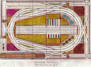 |
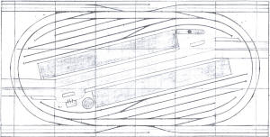
Grand Bayou |
368 |
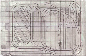
Last of a breed...hence the coffin shaped
building complex, this is an expansion of the square, original, single
loop layout. Better to use existing 4'-wide layouts for further
development of the use of these end treatments........(8>)....Geo.....
TrackLayer's note: this is the
first posted layout which was prepared entirely on the Mac. |
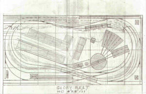 |
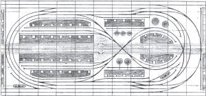
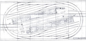
Glory Belt |
367 |
I was perusing the G&D file & came upon the
track plan & got the urge to do a takeoff of it as a 4' x 8' layout with
18" minimum radius. However, I had to use a 15" radius on the left inner
loop end, in order to keep the proportions in line.
A number of tracks have been added, including a diesel service in the
left front corner, as well as corner stub sidings & industry flats in
the other corners. Also steam service on a switchback from an added
industrial siding for the town area, which has also been added.
A major industry at the left rear has two tracks, so cars can be swapped
on site. The long siding at the left front is used as an interchange
track.
I included the turntable just to keep in line with the original G&D & to
be used if the layout were ever expanded, since operations really don't
require turning the locos & only one loco is required to do the
operation of moving cars from the interchange to the industrial sidings
& back. I would not build this layout, but it will be fun to run on
Train Player. |
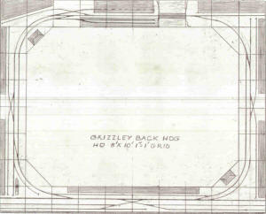 |
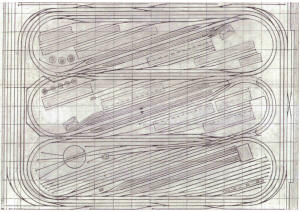
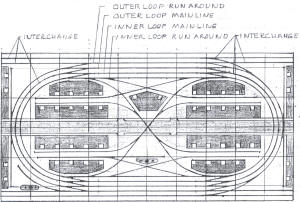
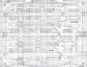
Grizzley Back Hog |
366 |
The Hog is based upon using a 4' x 8' sheet,
cut up into 1' wide strips & assembled into an 8' x 10' , open center
loop layout with a duck under entrance to the center. Thus the area of
useable space is the same as the original 4' x 8' sheet.
The attached layout is basically, double tracked version, but with some
of the track removed to create a single tracked layout with two passing
sidings. The other through siding, at the front, is used as a double
ended industrial siding.
The stub sidings between the main line & the industrial sidings at the
front, are interchange tracks. A service area is located at the left
front corner. The feed & seed mill complex is located at the right rear
corner, to the right of the bridge & a wharf at the center rear, to the
left of the bridge. The building behind it has the track inside, so as
to allow a full building. It could be a back ground building, like the
rest of those against the walls.
Two passenger stations are also included, at opposite corners, left rear
& right front. The rest of the buildings are a mixture of Walthers
Background buildings, or module buildups.
The minimum radius is 18", but as I mentioned, if the layout is expanded
outward to 9' x 11', the minimum radius becomes 24". Turnouts are Peco
Short, with 24" radius through the points & Peco Medium,with 30' radius
through the entire length & both have a 12 degree diverting route.
The base is 12" wide x 8' x 10', with corner gussets, like the original
Hog Layout. The design provides for all of the basics of the original,
except for the minimum radius, which is not a problem, as far as I am
concerned. |
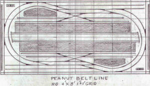 |
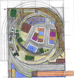
Peanut Belt Line |
365 |
Yet another variation, adding some
crossovers to gain more flexibility. |
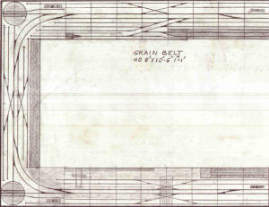 |
Grainbelt |
364 |
Grain Belt is in responce to the Pike City
Belt Line & includes a module terminal as well as a Grain Silo
Structure, using three Walthers kits.Continuous industrial complex flats
are located on three sides. Trafic is from the car float to the other
side & back, with switching in both directions.
Each turntable marks a terminal run destination. Trains run to the right
end & the loco uncouples & takes the crossover to get to the mainline &
back to the turntable. Then to the service track for fuel & sand.
The main yard switcher then pulls half of the cars & delivers them to
the carfloat ladder track & the float switcher spots them on the float
holding tracks. Later, when the float arrives, the float switcher
unloads the cars & delivers them to the main yard switcher, that spots
them in the main yard.
Later it will make up a train on the departure track & the road loco
will leave the service area, move onto the turntable & exit onto the
main, heading in the west ward direction. It couples onto the train &
after the air is pumped up & the brakes are off, it departs & will
switch the industries along the way to the other side. |
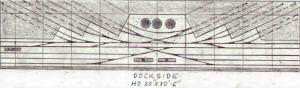 |
Dockside |
363 |
This one replaces # 17 of the "get me
started" group, of the same name. There is enough switching of cars at
the rear, that the volume of cars required (2), three track interchange
yards at the front. The central runaround & the left tail track will
hold (6) 40' cars.
The long runaround will hold (10) 40' cars. The 30" x 10'-6" size is
comparable to the 24" x 12' size of the # 17, area wise & all of the
turnouts are within 18" of the front, as are the uncoupling spots, so
manual reaching is in the ball park. |
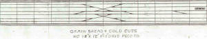 |
Grain Bread & Cold
Cuts |
362 |
The 18" x 12' size & the 4' long tail
tracks, plus the 5' long runaround are the primary elements that are
common to the Bread & Cold Cuts & the Grain Bread & Cold Cuts layouts.
Both have double stub sidings on the left front of the layout, as well.
The GB&CC adds crossings & three more sets of stub sidings to create a
Canyon Of Steel between the walls of two industrial building complexes.
The original set of stub sidings can become interchange tracks that
supply the cars for the sidings of the various industries.
This layout is designed to handle 50' & 55' cars. It can be shortened to
8' & still be functional. The service area & crossover will have to come
along with the shorter versions, of course. Three car cuts are the limit
of the central runaround, but the 5' long run around will handle (7)
cars. This will decrease with the shorter versions |
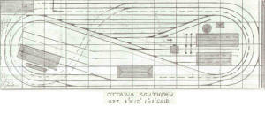 |
Ottowa Southern |
361 |
This is my version of the Ottawa Northern.
It mimics the original, but is a folded dog bone with hidden staging &
no reverse loops to worry about, while the Ottawa Northern is a basic
flat layout with no staging. Some industrial sidings have been added at
the right end & the left loop center. |
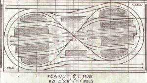 |
Peanut 8 Line |
360 |
Never combined a Peanut & a Figure 8 before.
Each interchange yard will hold (19) 40' cars, about what all of the
combined industries will hold, so the layout is close to being
balanced.Operation is "Point To Point Via Loops", with switching along
the way, in both directions, Service areas are in opposite corners. |
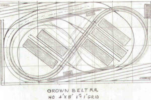 |
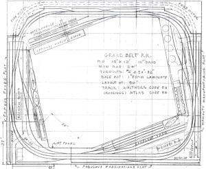
Grown Belt Railroad |
359 |
This is a variation of Lynn's Railroad That
Grows...with a more realistic grade at the rear & yards & service areas
at the front & rear of the layout. Operation is "Point To Point Via
Loops", with switching along the way, in both directions. |
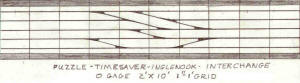 |
Timesaver
Interchange |
358 |
This is an O gage version of the combination
of the original Puzzle, Timesaver, Inglenook & what I used to call the
Double Inglenook, but have renamed the Interchange, since the design
does not have two seperate Inglenooks, as the name implied, but rather
two super imposed inglenooks that can only be operated as a single
Inglenook, one at a time & not both at the same time. The turnouts are #
4.5, with 12 degree frogs.
Each individual operating problem can be done, one at a time. However,
the Puzzle & the Interchange or either Inglenook can be operated at the
same time, by two operators. Or the Timesaver & the rear Inglenook can
be operated at the same time, by two operators. Of course, they can all
become part of one operation, using two locos, swapping cars, back &
forth between the front & rear of the layout, where industrial flats
provide designated locations for spotting individual cars.
This is another of my 2' x 10' series, that is usually for HO, but this
one is for O gage or On30. |
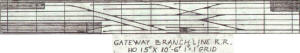 |
Gateway Branch |
357 |
One big improvement of the longer layout, is
the longer leads of both the car float & float yard & the main yard.
Now, (5) 40' cars & the switcher can be accomodated. Of course, the rear
industrial area has also been increased, so more cars can be spotted on
the industrial spurs. In fact, a new setout spur has been added to the
left end, fed off of the runaround tail track, rather than the run
around.
A three way turnout is used to increase the main yard's capacity & an
added crossover, off of the yard ladder track, creates an additional run
around between the car float lead & the main yard lead. The crossover
allows the yard switcher to spot the two extra float cars on the end of
the float lead, which is long enough to still accomodate the float
switcher & (5) 40' cars.
The crane services the spur next to the float lead, so there is no
interference with the float operations. The switchback spur, at the
front is for tank cars that load/unload to barges located along the
front of the layout, but not modeled.
Operation is the basic float to main line to main yard to industrial
sidings at the rear. The returns are from industries to float lead to
float yard & then to the float & off of the layout |
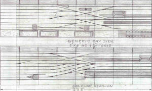 |
Generic Bay Side |
356 |
Two versions of a simple dockside switching
layout. |
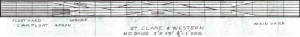 |
St Clare &
Western |
355 |
|
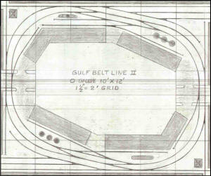 |
Gulf Belt Line
II |
354 |
This layout is suitable for endless
switching. Two small interchjange yards allow cars to be staged for an
operating session. Once these cars have all been delivered and the
pickups returned to the interchange yards, the waybills can be cycled
and the next session can begin.
A double track mainline and plenty of crossovers allow simultaneous
operation of two trains. |
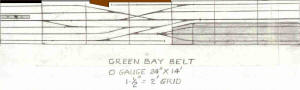 |
Green Bay Belt, |
353 |
Another simple car-float switching layout... |
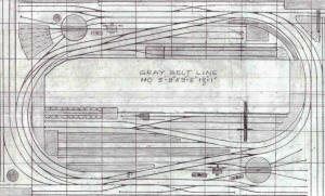 |
Gray Belt Line |
352 |
|
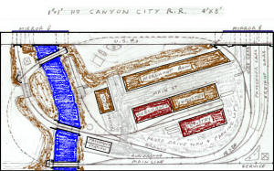 |
Canyon City RR |
351 |
This layout was inspired by a recent Model
Railroader project layout. The Original plan(the Turtle Creek Central)
suffers from many design flaws, not least of which is that both long
sides and one end must be accessible for operation. This means that the
absolute minimum space it occupies is 8 x 10 (10 x 11 is preferred). The
space would be much better used by an around-the-walls shelf layout.
On the Canyon City, all the switches are grouped towards the lower edge
of the plan, so the other three sides can be placed against walls. It
would still be necessary to be able to pull the layout out for
construction or maintanance, but normal operation can be performed with
only one long side accessible. Thus, the layout need only occupy half of
a small room rather than the whole room.
The back of the layout is framed with a raised hghway, behind which,
building flats would make a nice backdrop.The layout also has enough
hidden track at the back to hide a complete train, thus adding milage,
and allowing the layout to run with two trains instead of the
one-train-limit impoosed by the original plan.The siding capacity and
switching potential is also greatly expanded, and the very short
headshunt on the original plan is now long enough to actually be useful. |
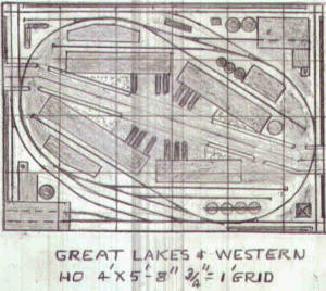 |
Great Lakes & Western |
350 |
This is what I would build, with 18" radius
curves, rather than the16", of the smaller layouts. The extra few inches
it takes will not make that much difference & the switching of cars on
the curves will be better. Besides, the overall car capacity is
increased, which means more operation. The two interchange tracks hold
(8) 40' cars each, not counting the switch backs, which add two at the
left & three at the right rear.
Operation is Point to point, with switching along the way, in both
directions, using two sets of car types, one "fulls" & one "empties",
that are swapped with each other at designated spots, on the various
industrial sidings. This eliminates the need for any paper work,
although any car forwarding system can be used to direct car movements,
during operations.
Buildings are scrath built using Walthers & Koler modular systems,
including the flats along the edges. The loco service area is located at
the left rear corner & is used for both interchange runs. All in all, a
complete layout. |
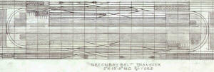 |
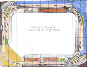
Greenbay Belt Transfer |
349 |
The Greenbay Belt Transfer is a Layout
Design Element Layout that was inspired by Tony Koester's article on the
subject. It has a three tracked car float at the left front, with a
capacity of (24) 40' cars & a two tracked interchange yard at the right
rear, with a capacity of (36) 40' cars.
Two back in passenger stations are featured & the passenger trains,
including the locos, also get shipped off of the layout, via the car
float. Dock side tracks are provided on both front & rear & industrial
complexes make up the center area. This could become an operator aisle
on an actual layout.
Added switching is provided by industries at both ends. |
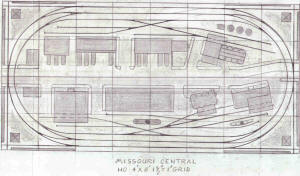 |
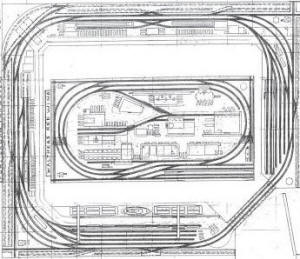
Missouri Central |
348 |
I was impressed by the St. Louis Central,
that was featured in MR, so I did this take off of it. Most of the same
buildings are used & in the same approximate locations, except for the
Grain Elevator. The outer sidings at the front & rear are not passing
sidings. Rather, they are interchange tracks that can be worked from
either end. Each holds (12) 40' cars & are used as the source of
traffic, in place of staging or a car float.
Operation is "Point to point via loop", with switching along the way, in
both directions, using two sets of car types, one "full" & the other
"empties", that are swapped at the designated spots on the industrial
sidings.
A single service area is located at the right front corner of the loop.
The small buildings at the left of the loop are a "White Tower
Restaurant" & "Bill's Glass Shop". The rest of the buildings are
obviously the Walthers basics from way back, plus a City Classic's
Warehouse & a Heljan Brewery Malt House, which were used on the St.
Louis Central, as well. |
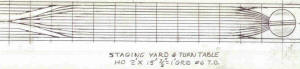 |
Staging Yard &
Turntable |
347 |
This is the latest for the staging yard
concept. The outer tracks are the through tracks & the straight
extensions on each side of the turntable are for double ended units that
don't require turning & are too long for the table. They use the second
track in on each side. All others get turned.
The loco storage areas on either side of the throat, can be service
tracks & be detailed. In fact, the entire scene can be detailed, instead
of hidden. |
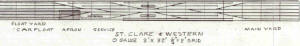 |
St Clare & Western |
346 |
This is my planned layout, for my basement,
up in Michigan. It is a take off of the carfloat operation that John
Armstrong featured in his original book on track planning. It is
composed of four 2' x 8' modules & features both the float switcher
using the runaround track as lead & the main yard switcher using the
main line as lead, so both can operate at the same time.
Also provides parking for the main line road loco,so it can do the
'Arrivial & Departure" operation. An industrial complex flat runs along
the entire rear edge & a second one is located in the center front. The
sidings there are for these industries.
Operation is the moving of cars from car float to main line to main yard
to industries & back to the float yard. After the float is unloaded, it
is loaded with cars from the float yard,.so it can depart, without any
delay.
The mainline road loco does the delivery & pick ups at the industrial
sidings, with trains that the yard switcher makes up & brakes apart,
using the main yard as it's operational base point. lots of action in a
relatively small space. |
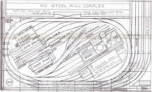 |
Steel Mill |
345 |
I decided to revise my original mill drawing
to better represent the steel making process, by making the Walthers
rolling mill a hot slab mill & double it's size & add a closed in ingot
mold top removal area in front & a blower bld. in back, plus a power
house behind the electric furnace. Also added a hot coil rolling mill &
cold coil rolling mill, at the rear, with hot slabs going in one end &
cold coils coming out at the other end.
Now the whole thing looks a lot better to me. At least the process of
going from coal to coke, (coke ovens), from coke & ore to molten iron &
slag,(blast furnace), from molten iron in bottle cars to molten steel
made into ingots, (electric furnace), which are made into hot slabs,
(hot slab rolling mill), which are rolled into hot coils, (hot coil
rolling mill), which are cooled & rolled into cold coils, (cold coil
rolling mill), which are shipped to the various manufacturers of steel
products, is depicted, in a somewhat simplistic presentation, but it
does includes the basics.
The Peachtreeshops layout prompted me to stay with my original layout
approach. The revisions only increased the size to 4'-10"x 8'-2" but it
would be better if built on a 5' x 9' base. That would allow the
inclusion of some of the support buildings, for service, rebuilding &
repair of the many items utilized in the process of making steel.
Of course one can fill whole basements
with this kind of modeling & still omit many of the operations. |
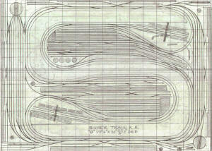 |
Super Train RR |
344 |
It is not real obvious, but if you squint
your eyes, you can see the "S" like Superman's logo, in the right hand
end of the Appalachian & Ohio RR, on page 47 of the May MR. That is
where I got the inspiration for this layout. The double ended staging
yard on the right edge & the peninsulas set the stage for the overall
shape, which is all that I was interested in. Coal roads are not my
favorites.
Of course, doing it as an "o" gauge layout was also part of the plan,
especially since the aisles got too tight fo an HO layout.Making the
3/4" grid = 2' solved that problem & gave me another "O" gauge layout
for the collection. The second staging yard uses my latest design, with
the turn table at the one end & the loco service & storage at the other.
Also ,adding the switching sidings along the wall, gives the operators
some diversion from just turning trains.
The service tracks are set up for diesels at both terminals, but steam
is serviced at the right front corner, just off of the turn table at the
through division point yard, which also has industrial sidings along the
back wall.
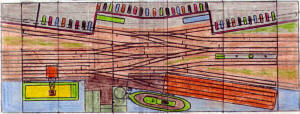
The Passenger terminals are designed for back in approach moves, so no
engine escape moves are required. The industrial sidings are off of a
separate main line & runaround, so they are more like linear layout
operations & free the other main lines from their switching intrusions,
with just a bit of the action encroaching on the main lines.
Passenger operation is from one terminal to the other & back, but also
includes trips to both, yards. Likewise, the container terminals swap
cars with each other, the one being a barge operation & the other being
a surface transfer, to & from semi-trailer mode & the trains also visit
both yards.
Additional road switching is provides by industrial complex sidings on
the other two walls. All in all, a Super Train R.R. that can actually be
built, in an average basement. |
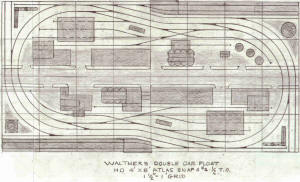 |
Walthers Double
Car Float |
343 |
Train Player has done the job of revealing
the flaw in the floatcar version of the original. As a result, I have
designed another version, with two floats, that takes care of the
problem that resulted when I replaced one of the original interchange
tracks with a carfloat
This is the Walthers Wharfside with two car floats & revised track work
to support them, mainly a float holding track that is not a part of the
outer loop. The original Wharfside had two interchange yards & no car
floats, so the yards could get away with having the outer loop as the
lead. However, when the one yard was made into a carfloat, the holding
track ended up too short, so part of the outer loop had to be used &
this just does not work. As a result, the float had to be treated as an
interchange yard, like the original layout. Hence this new design which
corrects the problem & provides for traffic to travel from car float to
car float with the floats also being interchanged with each other, on an
actual layout. This will keep the loaded cars moving in one direction &
the empties in the other, for through trains.
For local runs, as when running on Train Player, operation will be
"Point to point via loop", with switching along the way, in both
directions, using two sets of car types, one being "fulls" & the other
being "empties", that are swapped with each other at the designated
spots on the industrial sidings. This is the same as the original
Walthers Wharfside, except that the car floats & float holding tracks
replace the original interchange yards. This requires extra moves when
un- loading & loading the car floats, in order to keep them balanced,
thus adding to the operations. Road locos park in the right front & left
rear corner service areas, while the float switcher makes up a train on
the outer loop track with cars from from the car float, that has just
arrived. Then the road loco takes the train on the inner loop & switches
the industries in the center area.
When the train is finished, it arrives at the other float area & the
loco is cut off from the train & moves to the service area. The float
switcher takes over & moves the cars to the float holding track. It then
unloads the carfloat & makes up a train on the outer loop. The road loco
then takes the train & runs to the inner loop where it switches the
industries, while the float switcher loads the carfloat with the cars
from the float holding track. this completes an operation cycle.
Operation moves to the other carfloat area. |
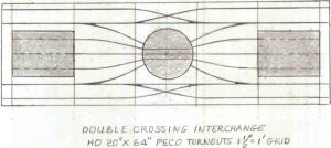 |
Double Crossing
Interchange |
342 |
This was inspired by the MRP 2004 article
Rear Platform & called a "traintable", which I recently reread. It is
much more involved, of course, but the central theme is using the
turntable as a substitute for turnouts.
This TT is only 10".long, so the diesel will have to be shortened to 3".
This can be done by selecting "Properties" & then changing the length.
The buildings are Walthers Back Shops, but they are used for
manufacturing purposes, such as food processing or appliances.
The (4) outer stub sidings are all interchange tracks, each one holding
(4) 40' cars that get switched to the two (3) tracked industries, one
car at a time. Lots of action in a small space. The curves are 24"
radius. |
 |
John Allen's Dockside |
341 |
Since I discovered Pikestuff Prefab Steel
Warehouse Walls make great Auto Assembly Buildings, as well as Appliance
Plants, I am using them more & more on my layout designs. Their low
height & flat roofs make them naturals for roof top parking, since there
is usually no room on my layout designs for parking lots.
This has not been a problem with back drop buildings, when the only
thing showing is the back wall of the buildings. The rest of the
building & the parking lots are assumed to be "out front", out of view.
However, in the case of loop plans, on island layouts, car parking is
often lacking, except on the streets, so I designed & built a parking
lot building that uses an elevator to get cars to the various levels,
including the roof, of course.
This led me to provide elevators for roof top parking, as well as drive
ways to the roof, inside of the buildings, out of sight. You just need
entrances at ground level & driveway wells at the roof tops. All of
which has me using the roof level of my buildings for display of my car
& truck collection.
I bring all of this up as an explanation of the rows of cars that are
shown on the rooftops of some of my plans, like this one, where the
roofs are extended to provide cover for the spurs into buildings.
This layout is a take off of John Allen's Time Saver Layout, hence the
name. It use wye turnouts to provide the shortest layout with # 6
turnout curves, for longer cars. |
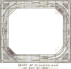 |
Hart At Michigan - HAM |
340 |
The Hog is gone, The Ham is home...The
layout has been relocated from Georgia to Michigan & it has been
industrialized & double tracked, to get rid of those two single-tracked
segments that were bottlenecks. Also, the lake is no more. In its place
a whole new area of rail activity, a virtual mini layout, that is a
switching challenge of its own, within the expanded HAM.
The Grand Trunk run from Detroit through Pontiac provides a prototype
that includes the varied industrial sites that are used on the HAM,
including auto assembly plants & car floats, not used on the Ham, but
used on the Corner Module Construction Layout, another candidate for the
Grand Trunk.
Platforms were added to each side of the passenger train storage tracks,
on the right, to create a back in terminal extension of the existing
corner station & a service area added at the crossing to the throat..
The tracks of the short yard, at the rear, were lengthened into a double
ended, arrival / departure track set up for playing "Division Point"
operations, with service areas at both ends, for East & West
terminations, using a common terminal point.. The single track siding at
the front has been double tracked & last, but not least, the corner
"Mainline" sidings have been added, as well. Now we have a layout, by
George! |
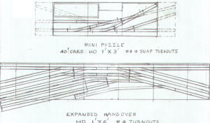 |
Two Plans For A Dorm Room |
339 |
These are the redrawn layouts, using Snap
turnouts, from Tyco or now, IHC, for the Miniest layout. Atlas #4
turnouts won't work, because the points are too long & the closure curve
is too large. Moreover, the frog angle is wrong, as well. The Atlas Snap
turnouts also will not work, because they use the same point system as
their #4.
All curves are 18"R. The IHC turnouts have shorter points, so they are
closer to a continuous 18" radius, through the closure rail & point
curve. The dotted extensions are required in order to get a loco & car
or two cars on either side of the runaround tracks, which will hold only
one car at a time. The turnouts have to be altered to 7" long, which is
not a problem, I do it often. Only (3)cars can be on the 3' long basic
layout: one at one end & two at the other, one of which is moved to the
open stub at the other end. Then the one that is there is moved to take
it's place & the third is moved to the other end, etc,etc,etc.
The Hung Over layout is an early version of an expanded Puzzle, but with
the tail tracks at an angle to eliminate any "S" curves & to make them
as long as possible. The car float is removable, so the hangout doesn't
count. Another spur can be added at the rear right end, & the float lead
extended, but I ran out of paper.
I would not build either one of these layouts with the fold down ends.
I'd rather stand them on end behind a door or under the bed. Likewise, I
would use dummy locos for hands on operation |
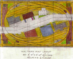 |
Walthers Mini Layout |
338 |
The April issue of MR featured a table top
railroad that got me to thinking about my own dining table, down here in
Florida, that we never use, except for the rare times that we have more
than one couple over for dinner. We normally take all of our meals at
the low kitchen pass through bar that separates the kitchen from the
dining area, so the table just sets there.
It is larger than the one in the article, so I was able to use an 18" r
loop. There are two interchange tracks that curve around the end & form
a longer storage area, just like my 4' x 6' layout, only smaller. I use
1" thick Dow blue rigid foam, which is more firm & stronger than the
pink stuff, so I don't have to add any frame or attach it to the table
tops or the tops of the cabinets or the wall shelfs that I use as the
base supports for my various layouts.
I also prefer to feature the Walthers street system on my small loop
layouts, rather than a senic backdrop divider & let the tall buildings
be the view block. Also feature Walthers buildings where ever possible,
with some modular ones from DPM or Koler.
Most of the turnouts are Snap, except the two in the center of the loop,
at the front & rear, that set the angle of the layout. That is what
produces the sharp angle of the street, of over 20 degree. There are two
service areas, so the loco can be serviced at the end of each run from
one interchange to the other & back, with switching along the way, in
both directions. Lots of prototype operation.. |
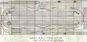 |
Grey Bay Transfer |
337 |
I combined the Generic Basic & the Generic
Car Float to create a loop version, Point To Point, with an interchange
yard at the front & a car float at the rear. Large building complexes in
the center & smaller ones at each end. Two different runarounds, so you
can decide which one you prefer to use. Either way, the car float has
its own switcher.
Ironically, you can still do The Puzzle Problem, using 50' cars & not
using any of the added turnouts. Or you can do a new version of it, with
a new
solution or two. |
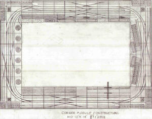 |
Corner Module
Construction |
336 |
This layout uses four 4' x 6' "L" shaped
modules for the corners & one 2' x 4' module at the front & rear. Two
corners are cut from one piece of 4' x 8', 3/4" thick ply wood. The
modules can be supported on legs, of course, but I prefer to mount them
on 1" x 3" strips along each wall, with angle brackets at the joints. !'
thick Dow blue rigid foam is used as the roadbed, with the track glued
directly to the top of the foam.
All traffic flows on & off of the layout, via the carfloat, although the
corner "main lines" can be used as interchange tracks instead of
industry sidings. In addition to the car float & float holding tracks &
main line yard, the layout features continuous industrial complex
buildings along all of the walls. These can be anything one wants them
to be, from food processing to appliance manufacturing to auto assembly
or just freight warehouses.
The front areas include a tank farm, shipping terminal, container depot,
grain elevators & dock side, complete with cranes, all located on the
waterfront, so ships could be added in the pit area, at the appropriate
locations, similar to the barges that are shown. |
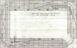 |
Generic Backaround
Staging |
335 |
The passenger trains emerge from the staging
& run around the layout & then back into the terminal. The locos are
serviced in place & later the trains depart & run around the layout &
then take a trip to the carfloat area & get loaded onto the float,
including the loco & the float then departs. They return with the
passenger trains & the trains are off loaded & run to the passenger
terminal. From there, they go back into the staging area, along the
walls.
Freight operation is basically car float to main yard to main line to
industries & then return to the float holding tracks & finally the car
float. A container terminal & large dockside terminal building are also
featured.
The large background building complex at the front is a food plant. The
one on the left wall is a small appliance manufacturer & the one at the
rear is an auto assembly operation. The one on the right is storage
warehouse that also features cold storage. |
 |
Toronto Harbour Belt |
334 |
|
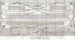 |
Quad Crossing RR |
333 |
This is one that I have been planing to do
for some time. It fits two linear layouts into a loop that is just a
skosh longer than they are (4") & it probably can be done in 8', but I
can live with the extra 4" length.
It is based upon the (12) 40' car capacity of the car float, the float
holding yard & the main yard, with (6) 40' car cuts being handled by the
tail tracks & the runaround. There is also a double ended interchange
track at the rear, so point to point via loop operation, with switching
along the way, is the norm. The multiple sidings will require several
car float loads, so there is lots of action on this one. |
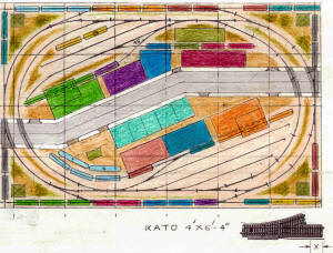 |
Kato 4x6 |
332 |
Kato turnouts have a 22.5 degree escape
angle, so that sets up the angle of the yards & the crossovers, which
produce the wider than 2" track spacing, The spacing would be even
greater, except I removed about 1-3/8" from the frog end, as shown. This
produces about a 3" track spacing, which we can live with. I do a
similar modification to the Atlas # 4 & Snap turnouts. The Peco are
already as short as they can be.
An inovation on this layout is the use of color to tie the cars to the
industrial siding spot locations. Note that there are two sets of each.
One set is at the industries & the other set is at the interchange
tracks, which are all of the sidings on the outer edges, including the
ends, which represent four different roads that do interchange with each
other & the central belt line that serves the yards & industries inside
of the loop.
The light blue (turquoise ) cars are tank cars & the red cars are
reefers. The green are gondolas, the blue are box cars, etc. This is
just a start up set up, since the cars at the interchanges can be in any
order. Only the industries remain the same, so a lot of variation is
still possible in the ongoing operation of the layout.
Obviously, there is room fo more cars to be added in the yards, but not
too many, because some of the yard tracks will be needed to do the
switch back moves, that require the cars on the tail tracks to be
removed, before the switch back track can be serviced. |
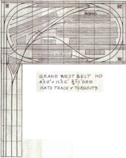 |
Grand West Belt |
331 |
I felt it only fair to do one up using Kato
track & turnouts, without any alterations to the turnouts. The 9" long
straight leg & the 22.5 escape angle cause the tracks to have 3"spacing,
but the curved leg fits into the same space as a curved section, so you
can drop a turnout into an existing curve. Great for pinwheels, or as I
have done it here.
Note that trains can head into the staging area from either approach &
the loco can cut off & run around to the rear & then shove the cars onto
the staging tracks. Also note the very long interchange track at the
left end & the 2" spacing the results from the placement of the turnout
way back at the rear of the main layout table.
The return loop connection is also included, as are the corner 90 degree
crossings at three corners. Passenger platforms are provided, front &
rear, for those who want to run passenger service.
The staging tracks each hold (10) 40' cars, except the long one holds
(20) 40' cars, for a total of (50) 40' cars. The seven corner sidings
hold (2) 40' cars each, for a total of (14) 40'cars. The four building
sidings each hold (7) 40' cars for a total of (28) 40'cars. The yard
holds (9) 40' cars & the short siding at the right rear holds (3)
40'cars fo a total of (12) 40' cars. The grand total of industry cars is
(54) 40' cars.
Using Atlas turnouts, three more sidings can be added to the staging
area, adding about 22 more cars for interchange. |
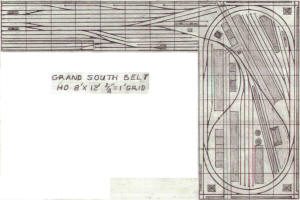 |
Grand South Belt |
330 |
See notes for GNB below. |
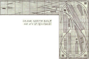 |
Grand North Belt |
329 |
The GNB is a take off of the MR project
layout being built on camera. In fact, I designed it while watching them
build the top & legs of both the 4' x 8' table & the 6' long add on. I
made my add on 2' x 8' to better fit on the Train Player Prodram. The
GNB is much more involved, but the origin of the design is obviously the
MR layout.
Operation is from one staging yard to the other, via the loop, with lots
of switching of industries along the way, in both directions. However,
the staging yards are developed into functional mini layouts,
themselves, with Arrival / Departure tracks, industrial sidings &
service areas, as well as yard tracks. More of less, mini terminals.
Another feature that is added is the "S" curved connection that creates
a return loop, so trains can change direction & locos can be turned, as
well. My signature corner sidings & numerous other sidings have also
been added, but the biggest change is the double track.
The passenger trains leave the station by moving forward to clear the
main throat turnout & then back up on either side of the return loop,
deprnding on which direstion it is going. Later, it will either head in
or back in, depending on the direction it was going.
The track work is designed for either Atlas or Peco, with 12 degree frog
angles, which produces 2" track spacing, rather than the 3" track
spacing that Kato 22.5 escape angled turnouts produce. This results in
being able to get much more track into a given area, as can be seen in
this design. One of the major reasons I use Atlas or Peco for the most
part, when designing my layouts. The Max. In The Min. |
 |
Rick's Four Loop Layout |
328 |
Another On30 layout, ready for Train Player.
This one was inspired by Rick Miller's layout that features four loop
layouts, each one with its own control unit & no interconnections
between the loops.
This layout is unique, in that the original is four individual loops,
with no inner connections, at all. It has four individual control units
& four different trains, one only on each loop.
Of course, that had to change, for the layout to be suitable for Train
Player operation, so a large number of crossovers were added to provide
for a multitude of operational variations, including the original
separate train on each separate loop.
Also, the interchange of cars between each loop, as well as point to
point operation from the car float to the long interchange track, off of
the outer loop, at the left rear of the layout, via the loops, with
switching of the industries along the way, in both directions.
Passenger service is provided with three passenger stations & the trains
can be shipped off of the layout, via the car float, including the locos
that will do the self loading & unloading. Steam service is provided at
the right hand inner loop & diesel service is provided at the small left
hand inner loop.
The car float has it's own switcher, but the plan allows the road locos
to do their own loading & unloading, as in the case of the passenger
trains, but also freights, as well, just as a change of operation, for
some variety.
Likewise, a number of main line routes are possible & multiple trains
can be run at the same time, so there is lots of action on this layout. |
 |
Division Point Layout |
327 |
Operation is for mainline trains to be made
up from float loads & sent to the staging area, where they can be
distributed to the various industries & then held on the center tracks.
Later, they will be run to the division point & have their engines
changed & turned for the reverse trip.
Arriving locos use the turntable at the opposite end of the layout, the
one they pass first. Extra locos can use the other facilities on the
other side of the layout, without interfereing with the float switcher
operation.
The Container Terminal is switched by a deticated switcher, using #4
yard track as the lead. This required using a three way turnout, but I
know you can handle that just fine.
The main yard can be switched from either end & the main yard
switcher(s) swap cars with the float switcher & the Container Terminal
switcher, as well. Plus, the road locos, in both direction. Lots of
locos involved with this one. |
 |
Jim Dill Empire Builder
RR |
326 |
The Study Layout has been extensively reworked & named The Jim Dill
Empire Builder in a spin off of James J. Hill Empire Builder, the Great
Northern passenger train named to honor the founder of the line. This
layout is dedicated to Jim Dill, creator of TrainPlayer & TrackLayer.
The action starts at the main terminal, with the passenger trains being
made up with cars from the passenger car yard, next to the passenger
terminal. They will travel over the entire layout, making stops at the
two through passenger stations, both on the way to the turnaround loop &
on the way back to the main terminal, where they will run around the
return loop & then back into the passenger terminal. The locos will cut
off of the trains & proceed to the loco service area to be refurbished
with fuel, sand & water. The freight trains will follow a similar plan,
except they will not stop at the through passenger stations, but will
stop at the industrial sites, located in between & switch the industries
along the way, in both directions.
Upon returning to the main terminal, they will also run around the
return loop & then pull onto the arrival / departure track & cut off
from their train. Then they will then run to the service area & be
refurbished with fuel, sand & water. Meanwhile, the main yard switcher
will break up & make up the trains. As an added operation, cars are
interchanged with the outer loop road, which switches the industries
located along the walls. That road, in turn, switches cars with the
third road interchange yard located at the left end of the layout. You
are free to name these roads to suit your own needs.
The treatment of the return loops, using the insulated crossing,
eliminates the need for a reversing section, since there are no
crossovers between the main lines & none are required, as yet. When the
passing sidings go in, on the other loop back areas, they will also not
use crossovers, but will just run along side of their adjacent
mainlines. Freights will use the through passenger station sidings to
let the passenger trains overtake them & will pull off of the main &
onto their own freight sidings at the other areas, so the passenger
trains control the flow of traffic, just as they should.
If actually building this layout, it would be prudent to spread the ends
of the loops to create aisleways for access. I may do a supplement
section to show this, but for the Train Player, access is not required &
it would not fit in this space, which is the max that I can fit into my
scanner. The outside loop is a separate railroad that interchanges with
the inside railroad at both ends of the layout, as well as with the rest
of the world, through an
interchange yard yet to be shown, when I do this on a longer sheet of
paper.
The other outer loop, at the rear, will be developed as an industrial
park & through passenger station. The inner loop, which is at a lower
grade, due to the overlap of the loop ends, will have an industrial park
& or a large industry or two as one of the roads main switching
operation. Also a through passenger station stop. The outer loop around
the walls,has industrial switching along the two long walls.The layout
of the inner road, provides about the longest run possible, without
having the track double loop itself, which was the goal that I set out
for. The double track, including the return loops, creates the longest
run, before a train uses the track a second time.
The freight yard lead is unique, in that it does not parallel the outer
loop end track, but crosses over & parallels the adjacent loop end.
Also, the steam engines do not interfere with the yard switcher when
traveling to the service area & turntable. Ironically, they only need
turning to get them to head into the roundhouse. They have to be turned
again to be headed in the right direction for departure.
Passenger trains take the left side upon arrival & run around the return
loop, then back into the terminal. This lets the locos free to back up
to the service area at the front right corner of the layout. Freight
diesels make a similar move, since all tracks converge at the front at
the left end of the layout.
This one will be fun to run on Train Player. |
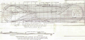 |
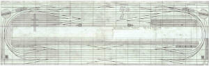
George's Nickel
Plate Road |
325 |
There is an extensive staging yard under the
layout that trains back into after turning around the hidden loop, Note
large arrow head on inner main line at the entrance to the hidden area.
The two crossovers in the main lines, allow them to be used for either
direction, around the left end curve & into the terminal. There are two
yard switchers at the left end, one on the outer track & one on the
inner track, so the center track is used for traffic in both directions,
to turn the trains
Arriving trains pass the yards & get turned, before stopping at their
yard arrival tracks. The locos then back up to the service area &
turntable & are turned to go into the round house, loco forward. They
have to be turned again to be going in the correct direction.
Operation is mainly the makeup & break up of trains, with stops at the
ice platform for train loads of refers. Other trains use the bypass
tracks.
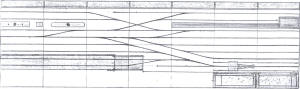
The heavy black line in the center is a low building that is used as a
view block, to separate the yards from each other, since they are
supposed to be located as shown in the straightened out version shown
below.
Note added relocation of the turntable that does double duty.
The transfer table at the loco shops will be a new challenge for you to
automate. It will provide a lot of action, if you can do it.....Geo |
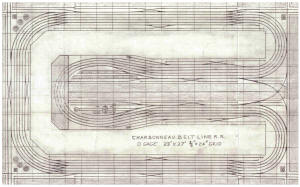 |
Charbonneau Belt
Line RR |
324 |
This layout was inspired by Norm
Charbonneau's beautifully done O gauge layout. It is designed to run
multiple trains on repeated laps of the mainlines, while switching local
trains at the many various sidings. The long sidings at the edges are
interchange tracks that supply the cars. Being on the edge, they are
easy to "fiddle" cars on & off of the layout.
There is an extensive service area for diesels & another for steam. A
feature of the layout is the hidden sharp loop ends that reduce the area
of the peninsula width. Since this is an urban layout, no mountains are
available for any tunnels, so the trains just run under a large
industrial building, instead.
Four mainline trains can run, unattended, while two way freights do
their thing on the outer tracks. The multiple crossovers provide travel
from one loop to another & back for all of the loops & the passing
sidings. Naturally trains can be run in both directions, at the same
time, some going east & some going west.
There are two turnouts that create return loops out of the peninsula
loop & they are off of the leads to the service areas, so locos can be
turned on the wyes at the left end of the layout. Minimum radius is 32".
An added benefit of the return loops is the ability of running out &
back operation in both directions. Essentially, the outermost track is a
point to point with a return loop at each end. However, the return loops
share the same track, making it an out & back design. Also, the design
requires a train to travel on all of the loops to get from the terminal
area to the outer interchange tracks & then back.
If built in HO, the layout would have to be a bit larger, in order to
increase the aisles to at least 24" min. Room size of 14' wide should do
it. |
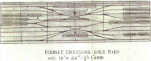 |
Double Crossing Gold
Bug |
323 |
|
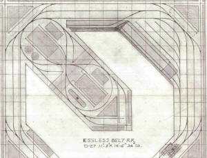 |
Essless Belt RR |
322 |
The Essless Belt RR uses the angled location
of the crossover to avoid the usual "S" curve that is formed by the
straight crossover. This eliminates any problems that can occur with
such sharp curves as are the norm with O-27 track. Because the locos &
cars are 1/48th scale, they require the wider track spacing that looks
odd to people that are used to seeing HO plans.
The float switcher & a road switcher are shown in the front right
corner, at the service area, which is supplied by a tank car for fuel &
a covered hopper car for sand. (not shown), that should be located on
the adjacent track. Trains are made up from the arriving car float load
& the road loco delivers them to the various industrial sidings along
the walls & inside of the figure "8" & on the point of the peninsula.
Cars in the float yard are loaded onto the float & it departs. Later it
returns with a new load of different cars. Several floats can be used to
keep up the flow of traffic, or the floats can be "fiddled" & the cars
exchanged for new ones.
Although the sidings next to the walls are through sidings, they are
used to spot cars on, all along the walls. These cars have to be removed
in order to service the end spurs, in each case, which adds to the
operation complexity.....Lots of action for two
operators.....(8>)....Geo.... |
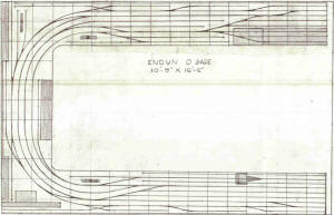 |
Endun O Gauge |
321 |
This one is O gauge, so the locos & cars
will be 10" long. The grid is 3/4"= 1'. The carfloat, runaround & mini
yard holding tracks all hold (9) 40' cars each, so that becomes the
train length, also. The carfloat is the primary source of interchange,
but one of the tracks in the yard at the other end can become an
interchange, as well. The industries along the walls can be anything one
wants them to be.
Three switchers & a road loco can be used. The first float switcher,
second float switcher, road loco & interchange yard switcher, at the
other end. Each switcher has its own lead & the road loco has the
mainline. The icing house & platform are located across from the packing
house, so the refers can be iced at the same time they are loaded.
This is one of the few "O" gauge layouts that I have done & I thank
Neville Rossiter, of Australia, for the inspiration to do it.....Geo |
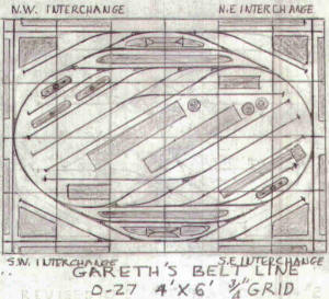 |
Gareth's Belt Line |
320 |
This is the latest O-27 layout & it is ready
to be included in the GB collection. It has four interchange locations
that can ship to one another, or the sites can be used as industrial
switching, as well. The stub sidings on the end service industrial
complexes As do the numerous sidings inside of th loop. An ice platform
is located in the front right corner of the loop area & a propane gas
depot is in the rear left corner.
An RDC train runs from station to station, while the freight goes about
its business, so there is lots of action on this small
pike....(8>).....Geo......
|
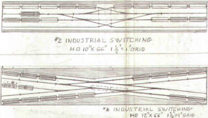 |
Industrial
Switching |
319 |
|
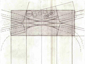 |
Gold Bug Steel Mill |
318 |
The final version of the modeled portion is
open at the front, since the rows of high mill buildings are not
included in the model layout. The portions that are included in the
model layout are low extensions added to the ends of the tall mill
buildings, so they do not block off the scene as much. The turnouts are
accessable as is the uncoupling of the cars at the entrance doors of the
buildings. The open hearth & the blast furnace are full height & form a
back drop to the scene.
Operation starts with the switcher
returning the covered coil car to the cold mill, from the interchange
track next to it. While there, it picks up the empty slab cars & moves
them back to the stripper area, located at the front left of the layout.
While there, the switcher picks up the empty Ingot mold cars & moves
them back to the openhearth, at the rear left, after which it picks up
the empty hot metal cars & moves them back to the blast furnace, at the
rear right of the layout. While there, it picks up the slag cars &
moves them to the slag dump,at the center left of the layout, where the
slag is dumped & then the cars returned to the blast furnace. Operation
is completed.
Now the next part starts.The switcher
picks up the full hot metal cars from the blast furnace & moves them to
the open hearth building, While there, it picks up the full ingot cars &
moves them to the stripper building. While there, it picks up the slab
cars & moves them to the #2 hot mill (via the cold mill building
extension). While there, it picks up the full coil car & moves it to the
interchange track next to the building extension. Operation is
completed. When that operation gets boring, a variation would be to have
two of each type of car & split them up so each siding has one at the
start. Then they would have to be swapped, one on one, except the short
cars, which can be two on two, or even three on three, with the very
short ingot cars. |
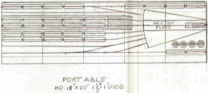 |
Portable Layout |
317 |
|
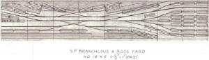 |
SF Branch Line & Ross
Yard |
316 |
|
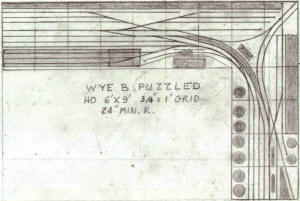 |
Wye B Puzzled |
315 |
The Wye Layout is a take off of the Atlas
plan that has a wye in the corner. However, that one has 18" radius
curves, which are a bit sharp for coupeling even 40' cars together on,
unless they have Talgo trucks with the couplers attached.
This layout has 24" curves & is designed for Peco turnouts, which also
have 24"curves through the closure rail. Atlas #4 turnouts, which are
really about #4-1/2, can be used, but the closure rails are about
18"curves, just before the frogs.
The 9' leg is a takeoff of my basic 8' long rear crossing module. The 6'
leg is designed to provide (3) stub sidings, (one of which is a switch
back) & the mainline tail track.
The long curved passing siding can be blocked in the middle, if one
wants to be restricted to using the short one, but it is there for when
you need it, when easier puzzling if desired.
Car holding capacities can be figured out using the 1' grid lines, (2)
40' cars per foot. The curved track segments of the wye will each hold
(2) 40' cars. The short runaround will hold (2) 40' cars.
Note that all of the turnouts on the 9' leg, except the wyes, are
connected to each other or the 24 degree Peco crossing. The atlas
crossing is 25 degree. Some of the Atlas turnouts need to have 1" cut
off of the frog end, to make them 8" long, to maintain 2" track spacing |
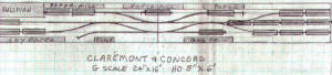 |
Claremont & Concord |
314 |
|
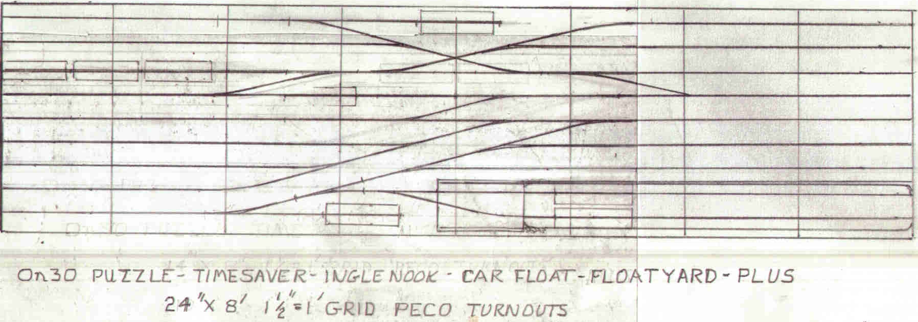 |
On30 Puzzle |
313 |
This one uses up the whole 2' x 8' sheet of
rigid foam base. It adds turnouts & a 25 degree Atlas or a 24 degree
Peco crossing at the rear, to add two stub sidings on each side & a
switchback in the center. These can be industrial, with a factory flat
along the rear edge, or interchanges or both. Or if it is too much, just
put single stubs on each side & delete the switchback.
We can still do all of the original puzzle operations of the three
primary puzzle layouts, by blocking off any tracks that are extra. But
now there are more meaningful operations that can be had on this
expanded version, that is truly a model railroad & not just a game
board.
With the track spacing reduced to 2", this plan can be used for an HO
layout with 50' cars, instead of the usual 40' cars that are normally
found on small layouts |
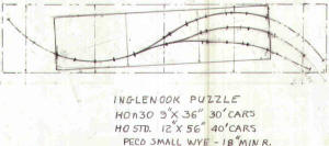 |
Inglenook Puzzle |
312 |
This time I did it right,..... I think.
Throw away the other ones, if you haven't already. This one has the two
sidings on the right side, where they belong. Both layouts show the Peco
small wye turnouts, so the short HOn30 version can be done in HO
Standard gage, as well.
I am already working on increasing the amount of tracks on the larger HO
layout, including Interchanges & a runaround, all in the same sized
base, 12" x 56" |
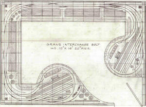 |
Grand Interchange Belt |
311 |
This is the latest layout. It was inspired
by the Model Railroad News project. layout room size. It is actually
designed to be built, using the basic 3/4"x 4' x 8' plywood base
approach, mounted to the walls, with a minimum of legs required & no
wall brackets.
Naturally it will have a 1" thick Dow Blue rigid foam roadbed, without
any added roadbed required. The base is cut away to provide maximum
access to the manual turnouts & manual uncoupling of the cars.
Operation is from loop to loop & back. The sidings along the walls can
be used as industrial setouts, or as interchange tracks, so the
operation is very flexible & no extra staging is required.
Passenger trains are parked at the back-in terminals, between runs. The
left loop has diesel service & the right loop has steam service, so both
kinds of trains can be accomodated.
I am looking forward to operating this one......(8>)....Geo..... |
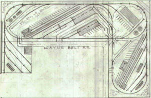 |
Wayne Belt RR (O
scale) |
310 |
Hi, Wayne...this is the final revision, at
least for now. The road way around the front is in phantom lines, just
to show where it would be, if it were being modeled. The revised
interchange yard at the left now uses 0-31 turnouts in order to take
advantage of the 3' x 3' size. Note that the front road way is modeled
on it. The yard holds (8) cars clear, but (4) more can be added using
the turnouts as storage. I added an industrial flat along that wall to
give a reason for locating the (4) cars there. They will have to be
moved, of course, in order to get at the other cars, but that just means
that they get picked up first, when making up a train for the road. The
two added buildings will each hold (2) cars. You will have to scratch
build them, but that is an easy job, using module construction.
The spurs with the kink in them, use 1/2 curve pieces to get from 30
degree to 45 degree, with a 10"straight between them & the 0-42
turnouts. This puts the parallel portions of the spur sidings closer
together & opens up the area for more detailing, such as adding a yard
office car, on the right end of the layout. On the left end, it
increases the area size of the "under construction" site that you
mentioned you wanted. You did not get back to me about the ice house &
platform, so I went ahead & added them on the left end of the layout.
Also show parking areas at all appropriate places, so you can display
some of your car & truck collection.
By the way, forget about running wires on the top of the foam. Just
drill a hole through the foam & the top of the base, next to the
turnouts & run the wires under the base & to the front & bring them up
from the bottom or drill a hole in the front of the base & feed the
wires through it to get to the switches on the front. Nice & neat & less
fussing around. |
 |
The Train Meet |
309 |
If you have seen this before, you probably
know the moves that are required to get the trains past each other & on
their respective ways.
There are actually two methods & one is more correct that the other,
depending on the nature of the trains...Have fun.....Geo |
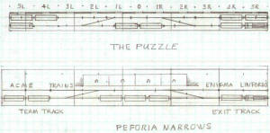 |
Peforia Narrows |
308 |
The Peforia Narrows was designed by Paul
Gittins (Wakefield Railway Modellers Society) and featured in his
article in the Peco Publications 'Continental Modeller' magazine a
couple of years ago. Paul says "the title is a play on words
relating to my other interest of modelling British prototypes in
exact 4mm scale P4 standards, the equivalent to P87."
George says about his alternative: This is a comparison sheet pointing up the
difference between the two layouts, mainly the exact locations of the
turnouts in both cases. In order to do the puzzle, using 40' cars, the
rear sidings each must be able to hold (3) cars, without blocking the
crossovers. This results in the runaround being able to hold only (2)
40' cars, without blocking the crossovers.
Although the original puzzle is to swap (4) cars with the other (4)
cars, another operation could have all (8) cars spotted at the rear, at
any of the (11) designated spots indicated by the numbers 0 to 5L & 0 to
5R.
Actually, in doing the solution, cars are momentarily spotted at all of
the indicated spots at one time or another, so it can be done, using all
(8) cars.
The Peforia narrows layout's rear sidings are too short to hold (3) cars
without blocking the crossover, so you can't use the same solution that
I used to solve the puzzle. There may be a way to do the puzzle setup on
the Peforia, but I don't know it. If you or your friends can do it, more
power to all of you. I'd appreciate hearing how you did it.
Meanwhile, you can see that slight differences in similar track plans
can create different operational oportunities & all of the plans are not
equal. Some are more equal than others. |
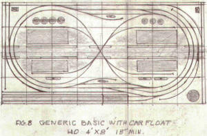 |
Generic Basic with
Carfloat |
307 |
This is the final design of this version.
You can create a grade by just propping up the right end of the layout,
an inch or two. That will give you the stretch & bunch action.
I kept it simple. It is based upon (16) 40'
car capacities, not counting the service cars, or the front right corner
spur, which will hold (4) 35' tank cars. That means that the layout can
hold (72) cars without crowding or blocking of the main lines.
It is a distillation of previous ideas &
provides a double loop, albeit, with a slight "peanut" offset & an
isolated car float package including the lead, apron, float & float
holding track. You can develop the center in any manner you
choose. I will be filling it in, but I want to do a figure 8 version
first, similar to the others, where there is no actual return loop &
access is at the right end only |
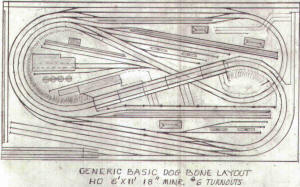 |
Generic Basic Dogbone |
306 |
Most of the features are obvious, except for
the street that runs under the elevated rail bridge work & through truss
bridge, ala the Detroit Fort Sreet Passenger Station approach over
Jefferson Ave, from my youth.
Traffic moves from car float to yard, to trains, to industries, to
interchange track at the rear of the layout & return, in a "Point To
Point Via Loop" with switching along the way, in both directions,
operation.
Back-in passenger station operation is from station to station, with set
outs & pick ups at each, on a continuous rotating run.
|
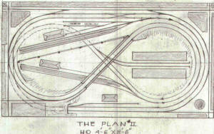 |
The Plan II |
305 |
This is the latest version of "The Plan",
with added everything. The passenger trains dominate the action. They
can be parked at the upper station & their engines can be parked at the
service area. They travel clock wise, out of the stations.
The single freight loco shares the service area & it's train is parked
on the interchange track at the rear of the layout. It is a double ended
track, so the freight can be set up to go in either direction.
The corner 90 degree crossings provide expansion in all directions, but
the "main line" tracks are used as setout sidings for this operation.
This layout has turned out to be another candidate for the Train Player
Program |
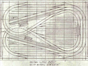 |
High-Low Belt |
304 |
The High-Low-Belt RR is folded dog bone,
over & under single track layout, with passing sidings at each end & a
common passing siding in the center area, that can be used as a yard
lead in either direction, at either end of the dog bone.
It features 90 degree crossings at all four corners, for future
expansion in all directions. By using the common passing siding, an
extended run can be realized that almost doubles the length of the
mainline over the basic loop.
Setting the outer crossovers to straight running creates two separate
loops, one inside the other. This will allow a train to run on the outer
loop & switch cars at the various stub sidings, while a second loco can
switch cars on the inner loop & run between the two reversing loop ends.
This version is going to be revised to add more setout sidings, as well
as service tracks & service supply tracks. It will probably be expanded,
width wise, in order to add interchange tracks at the front & rear.
One of the nice things about designing layouts for Train Player is the
lack of restrictions on size or access to the center of the
layouts.Created a true double tracked, folded dog bone layout, with the
double crossover that can be set for either extended run or for separate
loop operation, with no further changes to the crossover turnouts
required. This became a new, unique layout that is not to be found in
any of the books that I am aware of.
The High-Low-Belt has been revised to add a
forth track to the right end loop, with a double crossover between the
inner & the outer loops. When set to have the crossing in both
directions from both loops, the route is doubled, with no further
turnout activity required.
When the crossover is set for straight running, both routes will be
isolated from each other, at that location.
The revision required using O-31 sized radius track on the added inner
loop. Passenger set out tracks were also added at the stations. The
design is now ready for Train Player. |
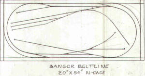 |
Bangor Belt Line (N
scale) |
303 |
Try it once with the point ends of the
turnouts cut off to form a smooth curve with the end curves......Also,
move the turnouts that join the interchanges on the ends, so that there
is enough tail track to spot some cars on the switch back track areas of
the main lines. |
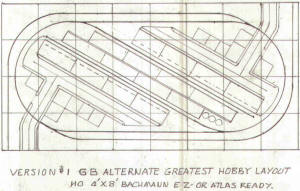 |
GB Alternate Greatest
Hobby Layout |
302 |
Hi, John,..your review of the Bachmann Track
Pack for the World's Greatest Hobby Layout, prompted me to do the
attached alternate layout, that uses all of the track & turnouts that
come in the pack, plus some additional straight sections.
You suggestion that, "No one is saying that every single new entrant
into model railroading has to build this exact layout", referring to the
World's Greatest Hobby Layout, did it for me.
The layout is one of the "Point To Point Via Loop Layouts, where the
operation is from one interchange track to another, with switching of
the industrial complex sidings along the way, in both directions.
The single track industrial sidings have buildings on both sides so they
do double duty holding different cars on the same spot, at different
times.
The interchange tracks hold twice as many 40' cars as the industry
sidings, so the total number of cars works out to be a balanced
interchange of cars, fulls for empties & empties for fulls.
By assigning specific spot locations for all of the cars, the required
moves makes for a very interesting operation. First, the operator
selects (8) 40' cars for a train & then runs it clockwise around the
loop. Next, the loco is uncoupled & then run solo around the loop in
order to get to the rear of the train so the industrial sidings can be
switched. Next the loco runs back around the loop so as to get in
position to swap the cars in the train with (8) new cars from the second
interchange track. These cars are switched with cars at the industrial
sidings, on the return trip back to the first interchange.
The cars in the train are swapped for the other (8) cars that were left
at the first interchange & these cars make up the new train that will be
exchanged for the cars at the industries. The whole operation just keeps
on going. |
 |
Pidgeon Street 2 |
301 |
Track by Bill Koehn |
 |
Misery Central |
300 |
|
 |
Midland Belt |
299 |
Track by Bill Koehn |
 |
live interchg.jpg |
298 |
|
 |
Belt Line
Transfer |
297 |
Track by Bill Koehn |
 |
Port Urban Transfer
and Walthers Red Wing |
296 |
|
 |
Pacific Great
Western |
295 |
|
 |
Double Crossing Belt |
294 |
|
 |
Baltimore & Ohio 26th Street
Yard |
293 |
Requested by a user |
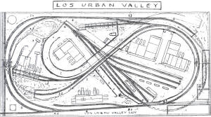 |
Los Urban Valley |
292 |
|
 |
Old Industry
Connecting RR |
291 |
Here is a simple one. It is one that I have
been looking forward to running, since it has all of the added features
that are lacking in Linn's original.#20, New industries Connecting R.R.
Linn's original had a lot going for it, but did not provide for
isolation of the switcher lead to the yard & had half of the industry
tracks served by the switcher yard lead. By using crossings, this
version has all of the industry tracks, save one,served by the outer
loop, which is the road loco track, so the mainline trains have more
switching to do on their way from one of the interchanges to the other &
back.
The revised plan moves the service area & provides a service track for
the coal tower, as well as reducing the turntable & round house size
to12". Interchange tracks & corner industry spurs have also been added.
These revisions provide for a more prototypical use of the plan & also
support two loco operation, independent of each other. |
 |
Grand Belt RR 3 |
290 |
This layout is cut from 3/4" ply as shown at
the right (not shown on TP layout). Two 4' x 8' sheets provide the
entire layout base which is mounted on 3/4" x 2" "shelf support strips"
along the walls, with brackets at all of the joints. NO LEGS! The front
edge fascia supports that area. Of course, 1"-thick rigid foam sheet
goes on top and no other roadbed is then required. Turnouts are manual
and uncoupling is with a skewer.
Of course, none of the above applies to TrainPlayer, but this layout was
designed years ago and is still a good one to operate, even on
TrainPlayer. Double track allows for travel in both directions by two
locos that trade places with two others held in staging.
Separate float lead and holding tracks, plus arrival and departure track
keep the mainlines free and crossings elimninate switch backs at the
industrial sidings. All kinds of traffic can be utilized. Even has en
engine service area with service supply track in the front right corner.
Broad curves and #6 turnouts make for smooth flow of cars and locos,
including those long auto carriers and container well cars. Busy, but
not congested. Fun to run. Go for it. |
 |
Trilap Transfer |
289 |
When I first saw the Lake District Ry plan
#15, I dismissed it as a fluke. Then I realized it was more of a fraud,
since there is no runaround, save running over the entire three laps of
the loop in order to get to the other end of a train and then running in
reverse in order to switch cars to the siding at Kadatz, which is a
facing turnout to the normal flow of the train, which is
counter-clockwise.
So I decided to revise the design around a modified 24" diameter loop
using 24"-18" curved turnouts to get the effect of the 15-deg crossing
of the original. Then the 18" diameter inner loop ends where transformed
into one inner loop that ran clockwise down to the right and under the
right side of the upper loop and the other inner loop that ran
counterclockwise down to the left and under the left side of the upper
loop. Both of these are joined together at the bottom "o" level.
Since I had already violated the maximum radius by using the 24"-18"
curved turnouts, I was not going to be restricted to the original
layout's overall size of 4'6" x 5'. Therefore, I was able to add more
track and turnouts and ended up with a much more versatile layout that
features two-loco operation: a car float switcher and a road switcher.
Also a ten 40' car capacity car float, holding tracks, service and
service supply tracks, double-tracked sidings on the upper level and a
small yard. Lots more operation in just a little more space.
The car float switcher unloads and loads the float while the road
switcher makes the run up to the upper level industries, swapping 9-car
trains of cars on each trip. The 10th car can go to the service supply.
The passenger loco backs up and couples onto the passenger cars, while
the float switcher moves back off of the main and into the "pocket"
track at the left end of the front of the layout.
Now the first freight train exits the tunnel and "arrives" while the
second freight train exits the high line tunnel and starts switching the
industries.
The cars from the first freight train are now loaded onto the float and
it departs. A "new" carfloat arrives and the cars are unloaded and
spotted in the yard.
Meanwhile, the second freight has finished the industry switching and
has hidden in the low line tunnel. When the float switcher is finished,
it will park in the "pocket" and the second freight train can arrive and
the action repeats itself.
This is what makes this layout special!
Most people would not use the layout in this way, and would miss out on
a lot of the action that is possible. Therefore we have to tell them.
The float switcher must also switch cars at the dock track at the right
front and the service track at the left next to the "pocket" track.
Sometimes, the trains just chase each other, with the passenger train
passing the freight on the front of the layout. Also, reverse direction
operation can be done. |
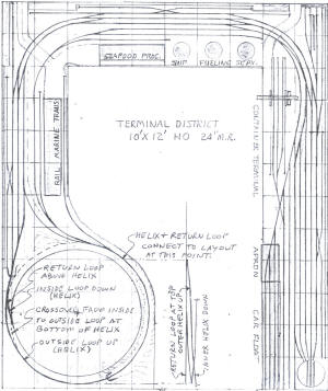 |
term_dist.jpg |
288 |
|
 |
middletown belt xfer.jpg |
287 |
|
 |
PM & I 2 |
286 |
|
 |
PM & I |
285 |
|
 |
Metro Lines |
284 |
|
 |
Grey Burro RR |
283 |
|
 |
Dock Side 1 |
282 |
|
 |
Riverside II |
281 |
|
 |
Variation on Ft.
Dodge & Elk City RR |
280 |
The loco makes up a train & proceeds to
run counter clock wise around the loop. It can switch any of the
sidings, since the train can be reversed & reversed over & over.
It finally "arrives" at the other
interchange & swaps its train for the cars at the interchange. The
loco can be serviced & then it makes the return run, back to the
first interchange yard.
At no time did the runaround sidings
need to be used, so I removed the crossovers, to clean up the
design.
|
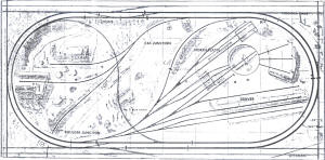 |
Variation on
Denver & Northwestern |
279 |
|
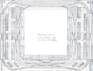 |
Toledo & Ohio |
278 |
|
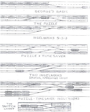 |
George's Basic and
Other Puzzles |
277 |
|
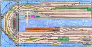 |
Metro Urban
Lines |
276 |
|
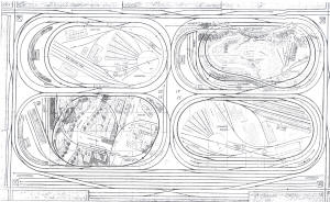 |
four_lyts3.jpg |
275 |
|
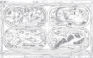 |
Layout Quartet 2 |
274 |
|
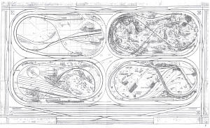 |
Layout Quartet 1 |
273 |
|
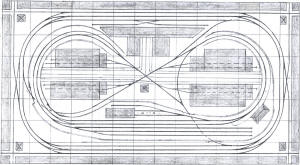 |
D.T. & I. |
272 |
|
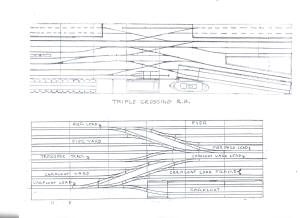 |
Triple Crossing RR |
271 |
|
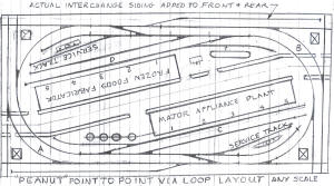 |
Peanut Any Scale |
270 |
|
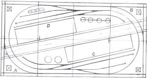 |
Peanut 2x4 |
269 |
|
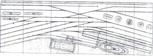 |
Noess Curves |
268 |
|
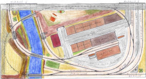 |
Canyon City RR |
267 |
|
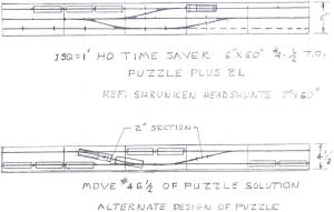 |
HO Timesaver |
266 |
|
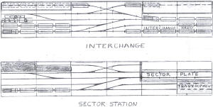 |
Sector Station |
265 |
|
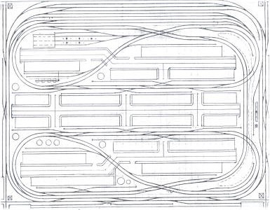 |
Urban Pacific |
264 |
Although the Ardmore, Cadosia & Fairmill RR
was the inspiration for my version of it, one has to look closely to see
the resemblance between them. However, it was the basic twisted dog
bone, folded over itself that first attracted me to it. Plus the return
loop on the one side.
I decided to incorporate the return loop feature in the mainline itself
and in two places, instead of just one. This increased the length of the
mainline run and forced running over the entire layout, with no cutoffs.
Of course, some alternatives were added, including runaround loops at
both front and back of the layout, as well as a separate loop all around
the outer edge. This is a belt line that exchanges with the main line at
the bottom of the main yard. The outermost track at the front is an
interchange track, as well.
Traffic on the mainline is setup up for right hand running, but it can
be reversed. The main yard lead is independent of the mainline traffic
and the engine terminal location on the other side of the mainlines
supports this, also. Although the outer loop industries are serviced by
the belt line, there is plenty of switching of industries for the main
line locos, in both directions.
Originally, there was a turntable and roundhouse, but the return loop
and some crossovers eliminated the need for them. Besides, this is an
all freight train layout set in the present, so diesels are the only
show in town. There is a fair sized service area for the main road and a
spartan one for the belt line. Except for the two roadway crossings in
the center, all of the others are roadway tunnels under the tracks. It
is neater and safer than surface crossings. Plus, easy.
Operations start with a train being made up for either direction.
Actually several can be put on the road, in both directions and then
have them continue running while one of them starts switching the
industries. The belt line operation starts with a pickup from the
interchange track at the front of the layout. Since it is a separate
line, it can do its industrial switching without any interference with
the mainline trains.
There is no runaround track on the right side, since the track is used
for the mainline yard lead. Runaround moves can be done at the other
areas adjacent to the right side, to get the turnouts into a trailing
position, in either direction. The roadways and buildings occupy areas
that could be operating space on a real layout. of course with the
TrainPlayer program, access is not an issue.
For now I'm calling the mainline road "The Urban Pacific" and the branch
line "The Outer Urban Transfer" or Up and Out, but I am open for
suggestions. |
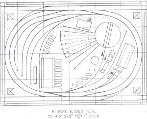 |
Ready Rider RR |
263 |
|
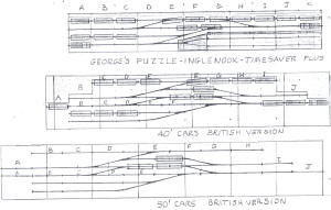 |
Puzzles 7 |
262 |
|
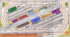 |
George's Bay Line |
261 |
This layout was built to run full sized
passenger cars & locos, so the minimum radius is 22". Because the cars
have Talgo style trucks with couplers attached, they do just fine on
these relatively sharp curves,
However, the 24" curved sections had to be increased to 24-3/8" to
provide enough side to side clearance for the 80' long passenger cars &
the outer curves are 26-3/4".
Passenger trains arrive & depart the layout, via the car float, as do
all of the freight cars. The float holds (7) passenger cars & an E-unit,
or (12) 50' freight cars.
In addition to the industrial freight sidings, the outer siding at the
rear is used as an interchange track, so there is just enough freight
car movements to keep me busy, what with all of the passenger train
traffic |
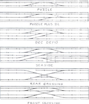 |
Puzzles 5 |
260 |
|
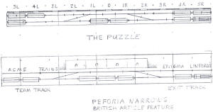 |
Puzzles 4 |
259 |
|
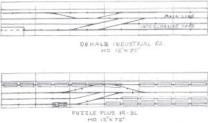 |
Puzzles 3 |
258 |
|
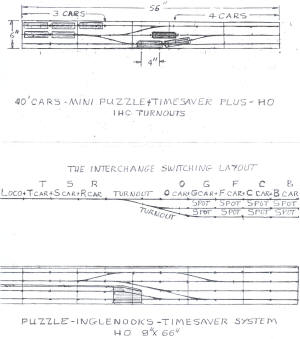 |
Puzzles 2 |
257 |
|
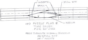 |
Puzzles 1 |
256 |
|
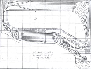 |
Ozark Lines |
255 |
|
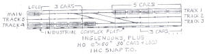 |
Inglenooks Plus |
254 |
|
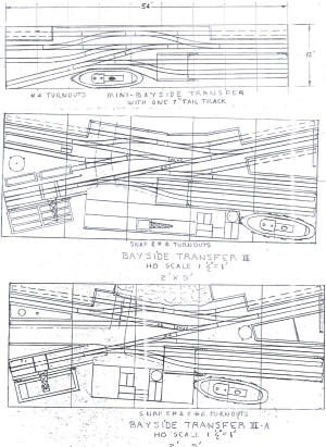 |
Bayside Variations 2 |
253 |
|
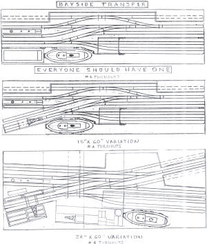 |
Bayside Variations
1 |
252 |
|
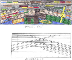 |
Bayside |
251 |
|
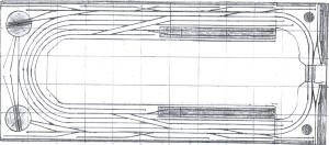 |
Twin Transfers |
250 |
The basic straight switching layout has the
following industrial sidings mainline, runaround and yard lead, main
yard, float holding tracks, car float and lead. When two are joined in
an "L" shaped layout, a turntable can be added in the corner. When they
are part of a "U" shaped layout, 2 turntables and loco tracks are
possible. Finally, when combined into a loop layout, all of the above
plus additional stub sidings are possible, along with continuous
running.
That is the story behind the twin transfers, that started out as a
single 2' x 8' switching layout. Cars arrive by float and are made up
into trains that travel over the loop, switching the industry sidings
and finally delivering the cars to the second float terminal. The floats
interchange, so loaded cars move in one direction and empties move in
the other.
There are more sidings, so there will have to be more carfloat loads
made up. |
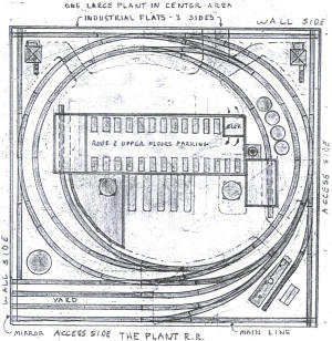 |
The Plant RR |
249 |
|
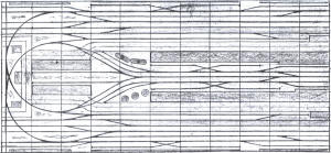 |
Switchback |
248 |
|
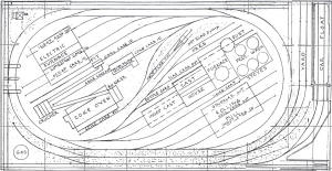 |
Steel Mill |
247 |
|
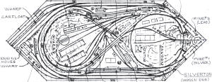 |
Nakusp & Slocan RR |
246 |
Canadian Pacific ran a carfloat service on
Slocan Lake that connected Slocan City with Roseberry and New Denver
located further north on the lake. The railroad joined Nakusp and
Sandon. I started to build an HON3 model of the Nakusp & Slocan RR using
only solid sheets of rigid foam, but never finished it. I still have the
partially finished base portion, sans any track being laid, but I still
have the turnouts and track for it. Another dream unfulfilled. Maybe now
I will be able to drive it on TrainPlayer.
I've included a schematic and an illustration which shows the elevations
from 0" on the left to 12" at the top. The section at the right shows
the 7" directly above the 2" of the upper and lower loop ends, so you
know that they are both the same 16" radius.
If that were 18", everything else would be just a bit larger, but it
would probably work out better and standard HO-scale locos and cars
could be used, instead of narrow gauge. You should be able to make that
adjustment. Most turnouts are #4 (actual) with some "snap" used in the
loop applications. (Why I suggest 18" min radius.) Making the base 4'-6"
wide should make everything else fall into place, size-wise. Overall
length will be about 11'-6" instead of 10', but that is not a problem.
I'm never going to build it, but someone else might.
Operation is from float to the mines, with stops at Three Forks in both
directions. Supplies get sent to Sandon and passenger service connects
to Roseberry to New Denver to Three Forks and Sandon.
Note: image was cropped so station names cannot be seen. |
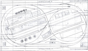 |
Rock Island Belt |
245 |
The Rock Island Belt 4' x 7' was motivated
by the Rock Island & Moline Belt Line, 4' x 8', layout #28. The trick
center loop return loops connected to the outer return loop create a
longer run than the usual dogbone style. Although the original is an
over and under design, mine is all at one level, which produced some
non-standard crossings, but they should not be a problem. The real
railroads are loaded with them, of course, just like they have many more
turnout sizes than we have. |
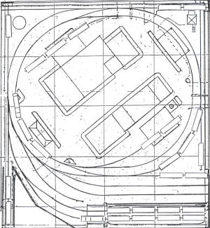 |
R&F RR |
244 |
The float loco has just dropped off 5 cars
on the outer loop mainline, taken from the holding track to make room
for the cars on the float. it has backed up to clear the main turnout to
the float lead, so it can run
forward to the float and start to unload the cars. Meanwhile, the road
loco has crossed over from the inner loop to the outer loop to pick up
the 5 cars dropped off by the float loco. Going forward with the cars in
tow, it will start to deliver them to the various industries in the
center of the loop and around the outside loop as false backs, along the
edges on 3 sides.
This is the first of 62 illustrations showing the movements of both
locos as they go about the job of moving cars from the float to the
industries and back. The second picture shows the float loco at the
float coupled
to the first car, ready to pull all four cars forward until the first
car is off of the float, then it will be uncoupled and then pulled
beyond the float turnout so the loco can return to the second track for
2 more
cars, etc. until 5 cars are off of the float. These will be delivered to
the #1 holding track next to the float. The remaining 3 cars will be
removed and spotted on the short holding track #3.
At the same time in the picture the road loco has pulled 2 of the 5 cars
forward to clear the turnout to the power house. Next it will push the
cars onto the spur and pick up the cars that are there. Then it will
pull the 4 cars forward to clear the turnout and the switcher will spot
the 2 picked up cars onto the 3 cars
on the main. Then after uncoupling the 2 cars and leaving them with the
train, the loco will move forward with the 2 cars to be spotted at the
power house until they clear the turnout again and can be shoved into
place and dropped off. The loco then pulls forward to clear the turnout
and then backs up to couple onto the waiting train of 5 cars. Next the
train is moved, either forward or backwards until it is at the turnout
to
the manufacturing plant where it will swap the 3 cars on the rear of the
train with those at the plant. When finished there it will return to the
same spot it started from and spot the train just clear of the cross
over, so that the float loco can pick up the cars, after the road loco
moves out of the way, onto the inner
loop via the crossover. This amount of action takes 17 pictures to
display. In order to move all the cars on the layout off of the layout
takes 62 pictures of 124 moves combined between both locos. These are
the
first two, only 60 more to go. |
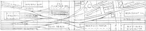 |
Progressive Rail
Terminal |
243 |
Normally I do not do such contrived layouts,
but the prototype is a hodge-podge of industries located in an
industrial park, that Jim Hediger did an article on for Model Railroader
back in July '02. (see letter below)
My version is more compact even, and does include a runaround. Also, I
designated two of the tracks as "interchange," since the prototype has a
long spur to the mainline that is used as the interchange and there is
no room for it on this layout.
There is an imbalance of car capacities between the industries and the
interchange tracks, so some "fiddle faddle" of cars will be required,
adding and removing cars as required. If I were doing any other
prototype, I would pick one with a carfloat, to avoid the problem.
Which brings up the point that on actual models of these plans,
carfloats can be removed and added, as part of the operation. Is there
some way that the TrainPlayer can consign floats to memory and then
retrieve them? I realize that the cars (and loco) can be deleted from
the float and new ones added, but that is not how it really happens,
either in the model or the prototype. Something for you to work on.
Also, do you do double slip switch turnouts? I am using one, if you can
do them. If not, I will work around it. |
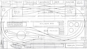 |
Port Terminal |
242 |
The Port Terminal joins my office layout
peninsula with the Walthers Way which was done as an alternate add on
for the latest MR layout and was not intended to stand on its own. It
worked out just fine in this application and got a couple of feet longer
in the process.
Likewise the port terminal version has a number of improved features,
such as a longer car float and float lead, a new pier with crane and
barge in the left front corner, a narrowed down rendering of the
terminal storage building, which allowed the holding track to get longer
and the addition of a tank farm and two sidings at the right end.
The Walthers street system fit right into place along the rear of the
original grain exchange and Kolber Mfg. The resulting 4'-6" x 8'-2" size
is just right for the TrainPlayer format, as well. |
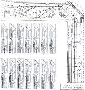 |
Pidgeon Street RR |
241 |
Pidgeon Street was a real carfloat location.
A friend sent photos and a rough sketch to me and requested that I do up
a switching layout for him. On the prototype, the float is located at
the end, down at the bottom of the picture, and extends out in to the
waterway. That took up too much room, so I relocated it up alongside of
the tracks. Otherwise, the tracks on the right are true to the
prototype.
However, the prototype is not an "L" shape. It is straight, all of the
way. Again, took up too much space, so I bent it. The angled sidings are
true to the prototype, but the background sidings and back around
staging are my doing.
The unloading sequence was done to show how the pros do it. Note that
the cars on the holding track, next to the float and on the right, next
to the industry siding, are not ever moved during the unloading and are
accessible after the float is emptied. That is the next operation, of
course. Then the loco switches the remaining cars to the various
industrial sidings. (Cars not shown but they are there).
This is another candidate for ovalizing, which I plan on doing, so this
is not really ready to become part of TrainPlayer. |
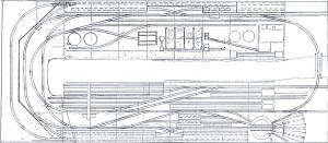 |
Paper Mill Transfer |
240 |
This layout was originally an "L" shape with
the left end joined at a 45-degree angle. That is why the track work is
so much more congested. Also the back around staging is now longer and
can hold 3 trains instead of 2. On the right end, a new roundhouse was
added and the straight tracks extended and turnouts added to the added
loop end, now the arriving passenger train loco can run past the station
and then back onto the turntable. The ice platform is extended, as well.
This shape uses the screen area more efficiently, plus the loop provides
continuous running, althought the layout can still be operated as a
point to point. |
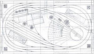 |
Old Industry
Connecting RR |
239 |
|
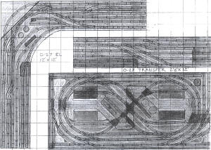 |
O27 Set |
238 |
The O27 layouts are meant to appeal to those
model railroaders that are in that gauge and scale. The three plans are
basic, but with a few twists that go beyond the norm for tinplate model
layouts. |
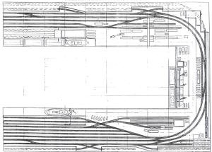 |
Manhattan Transfer |
237 |
|
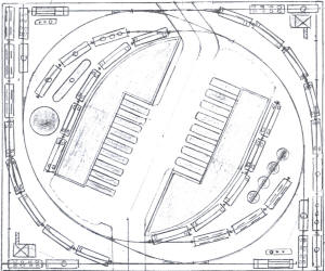 |
IHC 3-6 x 4 |
236 |
I decided to do some layouts that would be
take-offs of some of the 101 Track Plans, but with a bit more added to
make them more interesting to operate on the TrainPlayer system.
The smallest is the IHC 3'-6"' x 4' layout which has no comparable
layout in the book of plans. |
 |
IHC 4 x 4 |
235 |
The IHC 4 x 4 is a "point to point via
loop." It has no counterpart in the 101 book. |
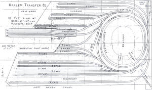 |
Harlem Transfer Co |
234 |
|
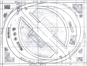 |
Gray Belt Line |
233 |
Entire loop is used for runaround moves.
Mainline spurs used as interchange tracks. "Point to point via loop
layout." |
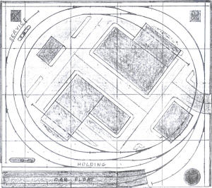 |
HO Grand Belt |
232 |
|
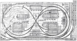 |
Grand Banks RR
2 |
231 |
Revised version of the Grand Banks RR
(see #203 for commentary) |
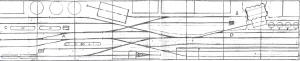 |
Endolin Terminal |
230 |
|
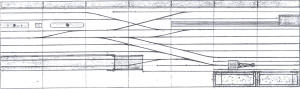 |
Dock Side |
229 |
|
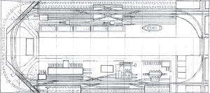 |
Double Double Cross
Loop |
228 |
The Double Double Cross Loop layout is one
of the "L" layouts that has been redesigned into a loop, so as to fit
better in the TrainPlayer format. In the process, sidings get added on
the right end and the staging track center section gets longer, so now 3
trains can be stored off stage, instead of just 2. |
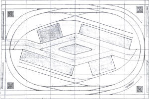 |
Central Valley
Line |
227 |
Point to point via loop layout(PTPVLL) |
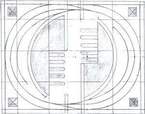 |
Bay State Eastern |
226 |
|
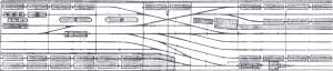 |
Bayside Plus |
225 |
George's Bayside Plus is a 7' version of the
6' original and has the alternate treatment at the rear. It should
replace the original and probably the Switchman's Nightmare should be
deleted since it appears elsewhere. I had just included it so as to show
a comparison between the two layouts and did not intend for it to become
part of my collection. |
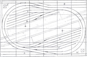 |
Basic Peanut |
224 |
Point to point via loop. |
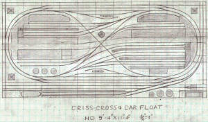 |
Criss Cross & Car Float |
223 |
The layout ended up 5'-4" x 11'-4", but I
got carried away & filled up the entire space!
It was a treat not to be confined to the 4' x 8' standard base.
That is what is nice about designing for Train Player. There is no
limitation on size. However, I don't want to get the cars & locos too
small while viewing the entire layout, so I will probably stay with a 6'
x 12' max.
That will accomodate the 2' x 8' modules of the "L" layouts, laid out as
"U" shapes or as the centers of loop layouts.
The first one was too close to the 4' x 8' version, so I redid it &
added a passenger station & platforms, as well as the ice platform at
the other end, which is what gave me the idea for the passenger station
& platforms, in the first place.
The passenger trains can be shipped off of the layout by the car float.
(just delete & replace). No storage required. Can we store trains for
recall? If not, it just takes seconds to create a new one.
The float & float yard have been increased in size & the new double
accessed interchange track eliminates the back up moves of the road
loco, at least on the float side of the layout.
This will be the best of the lot, I think,at least for now. |
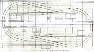 |
Wharfside |
222 |
The "Peanut" Loop solves the problem of
including an apron & car float on a 4' x 8' layout, while retaining the
three zones of operation that was developed with the 4'-6" x 8' layout.
using a conventional loop. This is the way to do it, rather than messing
with patching together a 4'-6" wide base, although it can be done with a
little added effort. But why bother? It's a good thing I haven't glued
down the track on the layout up north in Michigan.
The obvious Walthers buildings are in evidence, but the two long 5" wide
ones are Korber's, custom built to fit, length & height- wise. Also two
short business blocks from Small Town, just to add a little diversion
from industrial structures.
The street system is Walthers, with scratch built RR crossings at both
ends. The end of loop sidings are optional, but I like them for my own
use & they fit into the space very well, using 18" radius curves for
both tracks. They were first used on the 4' x 4' layout & proved out
there to be very functional, albeit, limited in capacity.
In the end, the S scale layout did help to decide on the approach to
take with the HO "Peanut" loop, by showing how not to do it. The angled
tail track of the switchback was just too limiting in the further
development of the layout, so the tried & true method of the crossover
turnouts coming out of the end loops was used, instead.
Sometimes the old ways are the best. |
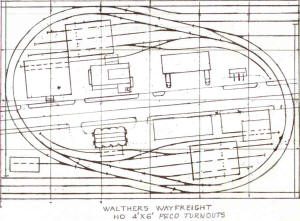 |
Way Freight |
221 |
This is just one example of another approach
to the Point to Point Via Loop Layout. The angled location of the loops
provides space for three interchange tracks on each side, while
eliminating the switch back to the right front corner siding that is a
part of the Study Layout approach.
Also, the center area is definitely different, although similar, with
the Walthers sized street running through the center of the layout.
This is about the maximum 4'-2" x 6'- 2" Point to Point Via Angled Loop
Layout. It is 1" larger on all four sides than a 4' x 6' layout, due to
the 1"framing all around & it is needed to fit it all in!
The name refers to the extensive use of Walthers buildings & road system
used. The interchange areas will hold (15) 40' cars each, so if one uses
the "empties at one & fulls at the other", system, they will not have to
remove or add any cars, unless they want to.
Because of the angle, any lengthening of the layout also increases the
width required to contain it, which is why I went to the "Peanut" shape
for the 4' x 8' long layout. |
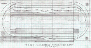 |
Timesaver Variation
Plus |
220 |
This is a finished version ... so you can
use it as is. The car locations are obvious & the 12" grid creates spots
for the 40' cars, (2) to a square. Nothing earth shattering, but lots of
potential operations, over & above the basic "game" layouts.
|
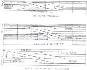 |
Switch Set |
219 |
I had done "George's Bayside," which is a
take off of Linn's "Switchman's Nightmare," before I found out about
TrainPlayer. I have been doing such "take offs" of MR track plans for
years. Since your announcement that you were going to do all of the 101
plans, I have reviewed the book and have concluded that not all of the
plans merit doing for the TrainPlayer setup.
The scenic effects of the layouts, such as bridges, mountains, tunnels,
etc. are lost when applied to the TPS and are usually applied in an
effort to justify what are often mundane variations of basic loops. In
the text, Linn suggests that many of the plans can be made more
interesting to operate by the addition of sidings and spurs for more
switching opportunities. Since you are using the plans as presented,
many switching options are not available, hence my take offs may be
desirable.
|
 |
Study Layout |
218 |
This one puts it all together. By adding
only 2" to each end, we can extend the interchange tracks around the
ends & add (5) more 40' cars to each end. The short yard track becomes a
loco fueling track & the service track is move to the outer corner on
the other side of the mainlines.
The industrial area on the other side, now the front, is different. A
new set of tracks have been added, via a 25 degree crossing that spaces
them to clear the walls of the buildings that they enter.
There are (68) cars shown & room for (3) more. Two locos are also shown
on the fueling tracks. Now two persons can operate together, each
controling their own loco.
There is enough interchange track car capacity to satisfy all of the
industry track needs, so no cars need to be added or removed, once the
layout is set up as shown.
This is the last one of this series, at least for now... |
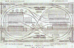 |
Single Criss-Cross RR |
217 |
This layout has four designated interchange
areas, two on each side, that overlap each other, in order to
accommodate switching from either end.
Six to eight car trains would be reasonable to work with, making sure
that the entrances to the interchanges are open, for the return of cars,
after the run from one interchange to the other, while using the center,
figure eight loop to switch cars with the industries in the center of
the layout.
Once a train is on the inner figure eight loop. a second train can use
the outer loop to switch cars at the sidings at each end, as well as
both loco service supply tracks.
Both locos can just run around the loop to get to the other end of the
train, so as to be able to switch facing siding turnouts, so neither has
to use the runarounds. Of course, if only one train is running, then
anything goes.
Four locos are shown, representing the four road names of the
interchange locations. The extra crossovers allow them to
enter & exit the service area from both ends, to get to the interchange
tracks.
Since the layout is only 7'-4" long, there would be room on an 8' long
sheet to add extra loop ends for interchange tracks. That would free up
the passing sidings on the sides, for other uses. |
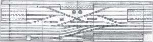 |
Sand Landing |
216 |
|
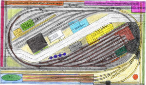 |
Riverside |
215 |
A color rendering of my original expanded 4'
x 8' layout concept to 4' 7-1/2" x 8' 1-1/2". The three colors of the
track are zones of operation. Yellow for car float, grey for mainline,
and brown for main yard and industries and loco service. |
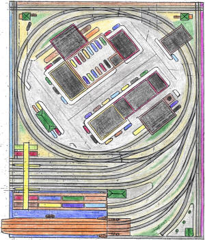 |
Port Union |
214 |
|
 |
Port Ogden |
213 |
I have been doing "take offs" of MR track
plans for years. My latest is "Port Ogden," which was inspired by Linn's
Port Ogden & Northern RR, layout #8 in the book. The yard at the left is
similar and the switchback main run is duplicated, but all else is
different. The added carfloat in place of the dock is the most obvious.
Also, the layout is all at one level, with a crossing replacing the
overpass in the middle. Each industrial siding at the rear will hold 4
40' cars, as will the other (3) in the central area.
|
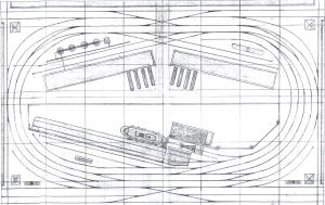 |
Port Layout |
212 |
I took one of my basic 2' x 8' layouts and
introduced curved track at each end to form a double track oval main
line. The main yard is only two tracks, but they are long enough to hold
14 cars, which is the car float's capacity. It took three tracks for the
float yard to hold 14 cars.
The float lead and main yard lead will clear 7 cars, which is good for
this size of a layout, 5'-4" x 8'-4". I plan on splitting it lengthwise
and adding a 1' wide "operator" space in the center and a drawbridge at
the right end to provide access to the basin from the outside world.
That will also re-proportion the shape to better fill the computer
screen.
However, that will require a 75% reduction in the plan in order to fit
it on a 8-1/2" wide sheet, so I can run the Xerox copy. That will cause
the scale to become 3/32"=1" and 1-1/8"=1' grid, just to keep things
straight.
Ironically, I would not consider building this layout. But I think it
will be very good as a Train Player. The second siding in each corner
can be used as one of four interchange tracks for running a
point-to-point via loop operation, as well as momentary setout tracks
while switching the
industries.
Two loco service tracks are provided, one for eastbound and one for
westbound. Two corner interchange tracks are also provided. The gas
storage tank will require tank cars and the plastic pellet silos will
need covered hoppers. The coal or sand barge will need drop-bottom
gondolas and the manufacturing plants around the outer edges will need
just about any kind of car, depending on one's imagination.
This kind of layout should appeal to the "game" oriented youth, as well
as old timers, like myself. I can hardly wait to get back to Florida,
just to try it out.
|
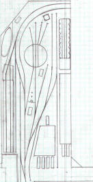 |
Office Layout |
211 |
This is a print of the right end of my
office layout. It could become one side of a loop layout. I may do that,
when I am up north.
I figured it was time, to draw the latest track plan, as it is shown in
the photos. All previous plans were slightly different, but this one is
pretty accurate. Turnouts are mostly Snap, with an 18 degree escape
angle. The turntable leads are # 4-1/2 with a 12-1/2 degree frog. The
peninsula is 30" wide & 72" long, however, the section extends 24" into
the adjoining section, so it is actually 8' long.
The track functions are fairly obvious, except the inside curved one,
which is used as a departure track. I have the add on for the grain
elevator, but it is still in the box. The turntable is from AirFix & is
older than dirt, but it is my favorite. I wish I could get more.
The roofless building at the right is scratch built using Tall Town
building windows, Walthers brick sheets & Evergreen strips for the
framing & corrugated sheet material for the roll-up doors.
The flat at the rear is 3/16" core board with xerox copies glued in
place. I use that approach on about 50% of the layout. The original is a
computer printout that I had made when I was still working at Ford
Motor. One of many perks, that I enjoyed.
The other backdrop buildings are either Korber or DPM module wall
systems, except for the passenger station, which will be made using Tall
Town windows. Except for the Atlas three stall round house, located at
the other end of the layout, there will be no other large buildings on
the layout.
All of the trackwork is completed, including the hidden staging, back
around tracks, located behind the continuous industrial complex building
flats. However, there is much to do, when I get back up north this
spring. |
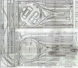 |
Metro Urban (Original) |
210 |
|
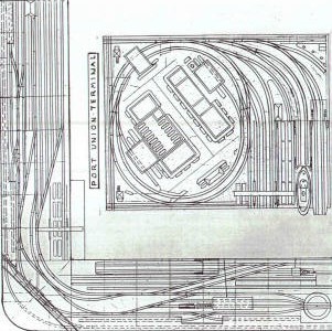 |
Metro Urban |
209 |
|
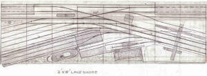 |
Lakeshore |
208 |
This is the largest version of this theme. I
have it installed on the right end of my basement layout. The yard
tracks at the left are blended into the rest of the layout & they become
the engine service area.
The two float holding tracks are lengthened & the first yard track
becomes the arrival track for freight trains that are bound for the car
float, which all of them are, eventually.
The next 8' long section to the left holds the engine service area
tracks, a 14" turntable, sans any round house, & the right end of the
passenger station's (6) tracks that all run into the turntable, so that
all arriving locos are turned upon their arrival, before proceding off
of the table & on to the service tracks area.
That has nothing to do with this presentation, however. This is just the
basic carfloat to yard to industries & back, layout operation, but with
a container depot included, at the right.
The industry in the back can be almost anything. On mine in the
basement, it is the receiving & shipping area of an auto assembly plant,
but doubles as a food processing plant, with a change of traffic & car
types.
This is one of my favorites, which is why I built it. |
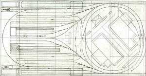 |
Harlem River |
207 |
This is the latest version, with the
separate float lead added to the #2 float exchange. This layout is
actually smaller than the prototype version, which is 5' x 9', rather
than 4' x 8' & this one has a lot more operation, including a passenger
train that parks in the front center area, on both sides of the
passenger platform, while the engine is refueled at the center servicing
area.
There is also an ice house & platform on the other side, across from the
passenger station & platform. Plus a diner just off of center of the
layout & cranes & barges at the end, behind the car floats, on both
sides.
The double loop is a take off of my original 4' x 4' with all of the
same buildings & streets, but with two "pinwheel" leads, instead of just
one & the yard & float relocated. I'll send a photo of that one.
Name changed to Harlem River Terminals to avoid any confusion with
Harlem Transfer or the Other Terminals located on the Harlem River. The
plural is because there are two of them on the layout & operation is
from the # 1 float interchange, on the near side to the # 2 float
interchange, on the far side, via the loops & vice-versa, with switching
of industries along the way, in both directions.
They could be considered East Side & West Side (of the river) which
would support the movement of the carfloats from one side to the other,
although the actual locations are not supportive of this, but that's
where our imaginering comes into play.
Of course, the loop of track that connects them, is another matter, but
that is the dilemma of all small loop layouts. One just has to pretend
that the trains change identities when they pass the mid-point of the
end curves of the outer loop.
Once at the new location, everything falls into place, more or less. It
is as much as can be expected, when dealing with a small loop layout,
but it would seem to be better than none at all.
If there were a view block down the center, it would help with the
rouse, but one can create a mental view block, if one wants to. |
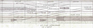 |
GTC&O |
206 |
This is actually two layouts in one, both of
them sharing the interchange yard. The GT side is straight forward,
operation wise, but the C&O side is a bit of a puzzle, involving having
to split the (10) 40' car train into (2) parts, after it "Departs &
Arrives", after traveling only a few feet.
That is why there are extra tracks & turnouts along side of the C&O main
line. The road loco has to run around the train, from the road engine
area to the far left, at the start.
Once it arrives at the interchange, the cars at the interchange have to
be removed, which is where the extra tracks come in. Then it gets more
complicated, but it works out in the end.
I built this one & have it set up in my basement, as part of the
basement layout, using the GT main & second track, with the crossovers
that form the runaround, as a second main line.
I originally was going to locate a container depot in this area, but
have already got one at the end as part of the LakeShore
2' x 8' module, which is located at the end of the basement layout. |
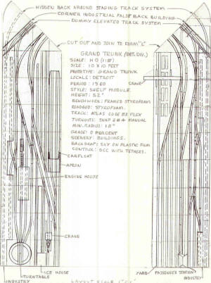 |
Grand Trunk |
205 |
This was designed for the Xerox copy to be
cut apart & joined at the corner to form an "L" shape layout. However,
looking at it as a Train player, the two parts could be joined, as is,
only closer together, so as to form a more narrow rectangle form, that
when rotated, would fit into the normal computer screen rectangle.
I think I am on to something here .... the "L" shape can become a narrow
"U" shape, laid on its side, about 5' x 10', with 1' of aisle forming
the "U". That shape would fit in, just like the 4' x 8', proportion wise
& just a little bit larger, all around.
I have over a dozen "L" layouts in the Urban News series, that could be
redone into the "U" shape. The advantage is a larger image & all
switching action is from side to side. |
 |
Grand Belt |
204 |
This layout is a breakthrough for me. Since
it is designed for Train Player, there is no need to be concerned about
"duck under for access" or extensive staging tracks.
The only staging track is the outer hidden loop with the multiple
entrances & exits. Since trains can be created & deleted in a wink of
time, you just need to have a "stage entrance spot", for arriving trains
& a "stage exit spot, for departing ones.
There are so many ways to operate on this layout, it is going to take an
instruction manual to cover it all.
It has a car float & float yard, a main yard with separate lead, icing
platform & on line loco service, on one side. The other side is a
"Canyon Of Steel" with industrial buildings on both sides of the main
line & runarounds.
The ends can be passenger station stops for trains that come from & go
back to the hidden loop & then are deleted. Likewise any kind of train
can be created, run & deleted. |
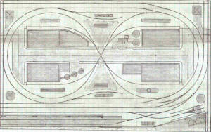 |
Grand Banks |
203 |
This layout has a single interchange track
on each side, next to the outer loop. The car float & float holding
track are an add on to the original pike. Cars from the car float are
placed on the interchange track. Cars on the float holding track go on
the float.
Operation is for traffic to travel from one interchange to another, with
switching of industries along the way. This requires some bypass/lap
running, due to lack of space, but that's where imagination comes into
play.
Placing the interchange tracks on the outside edge of the layout, as
part of a mainline that can be used to expand the layout, gives
credibility to their function as a connection to the rest of the world.
The layout has an outer oval & an inner figure 8 with only two
connections, both at the same end of the layout, with trains running in
one direction, when traveling from loop to loop.
Using 18" min. radius for the inner & 20" for the outer, provides space
on each side of the layout for the interchange tracks in the 22" radius
space.
The loco service areas are off of an outer loop connection to the inner
figure 8, so both can use them. Typical operation would have a loco
leave the service area & pick up the cars from the nearby interchange.
Then the train would run around the outer loop, passing by the other
interchange track & then continuing on around the loop to the crossover
onto the inner figure 8, stopping along the way to switch the trailing
spur sidings on both inner & outer loops.
Then the loco leaves the train on one end of the inner figure 8 & runs
around the other end to arrive at the rear end of the train,
effectively running around the train without actually doing it. Now the
train retraces its route, stopping to switch the trailing
sidings, that used to be facing, & crosses back over to the outer loop,
switching the trailing sidings there & ends up spotting the
train on the runaround track. The cars on the second interchange track
are pulled & replaced with the cars in the train. The new
train is spotted on the inner runaround track, clearing the outer
mainline. That ends the westbound run.
Next, the loco goes to the service track on the west side of the layout
& gets sand & fuel while the crew chows down. After lunch, the loco
picks up the waiting cars from the runaround & returns back along the
route, switching the trailing sidings on both loops & ends up back at
start, after spotting the train on the interchange.
As a diversion, the loco can run around to the other side & start there.
Or a second loco can start from there. Either way, a new operation will
unfold, wherein the train will travel from one side to the other, via
the inner figure 8 loop, completing a point to point run, on a loop
layout.( with a bit of imagination, of course). |
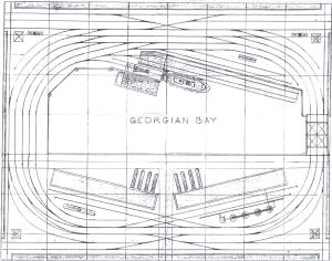 |
Georgian Bay |
202 |
|
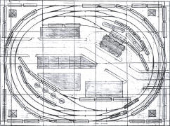 |
First Layout |
201 |
|
|
George Baustert Layout Gallery
|
|